Property measuring device for object to be measured and property measuring method for object to be measured

a technology of property measurement and measuring device, which is applied in the direction of instruments, specific gravity measurement, material magnetic variables, etc., can solve the problems of limited use of such acoustic waves, achieve high-reliability extraction of electric signals, and facilitate extraction of electromagnetic fields generated by measurement objects.

Active Publication Date: 2014-06-05
JAPAN SCI & TECH CORP
View PDF12 Cites 10 Cited by
  • Summary
  • Abstract
  • Description
  • Claims
  • Application Information

AI Technical Summary

Benefits of technology

[0021]According to a property measuring device for measuring a measurement object of the present invention, extraction of the electromagnetic field generated by the measurement object becomes easier as compared with the case where the acoustic wave is not amplitude-modulated or frequency-modulated, since the acoustic wave to be emitted from the acoustic wave emitting portion is the amplitude-modulated acoustic wave or the frequency-modulated acoustic wave. To state it differently, according to this property measuring device, it is possible to highly reliably extract the electric signal to be measured from the electromagnetic field noise or the like generated by the acoustic wave generating source.
[0022]In addition, according to a property measuring method for measuring a measurement object of the present invention, since the acoustic wave to be emitted is the amplitude-modulated acoustic wave or the frequency-modulated acoustic wave, extraction of the electromagnetic field generated by the measurement object becomes easier as compared with the case where the acoustic wave is not amplitude-modulated or frequency-modulated. To state it differently, according to this property measuring method, it is possible to highly reliably extract the electric signal to be measured from the electromagnetic field noise or the like generated by the acoustic wave generating source.
[0023]Further, by executing a property measuring program for measuring a measurement object of the present invention, extraction of the electromagnetic field generated by the measurement object becomes easier as compared with the case where the acoustic wave is not amplitude-modulated or frequency-modulated, since the acoustic wave to be emitted is the amplitude-modulated acoustic wave or the frequency-modulated acoustic wave. To state it differently, according to this property measuring program, it is possible to highly reliably extract the electric signal to be measured from the electromagnetic field noise or the like generated by the acoustic wave generating source.

Problems solved by technology

However, the use of such an acoustic wave has been limited to inspections or diagnoses of a mass density distribution and elastic property of a measurement object.

Method used


Image

  • Property measuring device for object to be measured and property measuring method for object to be measured
  • Property measuring device for object to be measured and property measuring method for object to be measured
  • Property measuring device for object to be measured and property measuring method for object to be measured

Examples


first embodiment

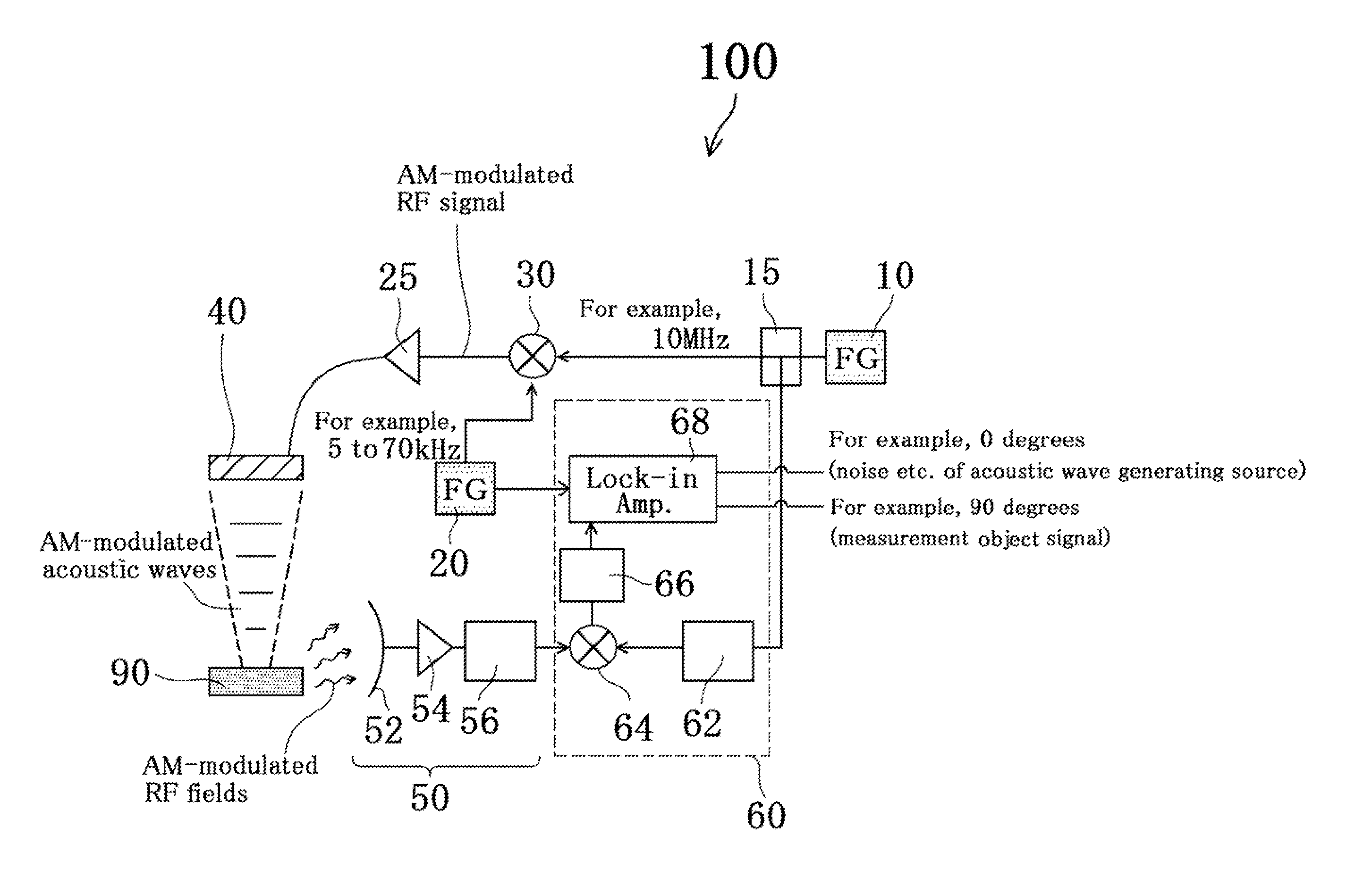
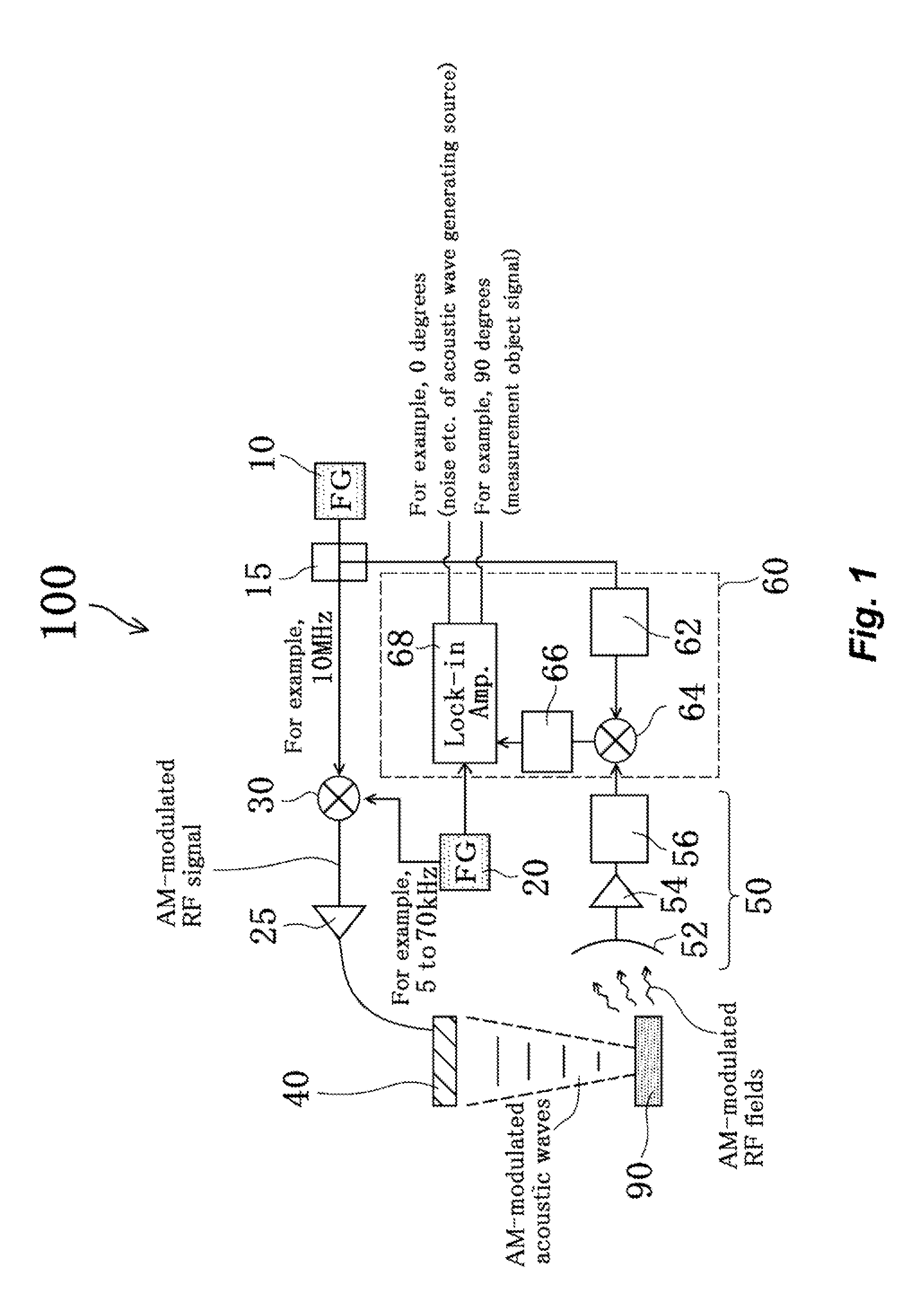
[0063]FIG. 1 is a configuration diagram of a property measuring device 100 for measuring a measurement object according to this embodiment (hereinafter, simply referred to as “property measuring device 100”). Since the drawing is a schematic drawing, a controller for controlling each configuration portion and / or peripheral equipment or a peripheral device including a computer connected to each configuration portion and the controller is not illustrated in FIG. 1. The same is also applied to the drawings illustrating configurations of a property measuring device for measuring a measurement object different from that of this embodiment in the present application.

[0064]As illustrated in FIG. 1, the property measuring device 100 according to this embodiment is broadly divided into three configuration portions.

[0065]First, a first configuration portion is an acoustic wave generator 40 for generating an acoustic wave emitted to a measurement object 90. In this embodiment, an amplitude of ...

second embodiment

[0096]A property measuring device 200 for measuring a measurement object (hereinafter, simply referred to as “property measuring device 200”) of this embodiment is the same as that in the first embodiment except that the receiver 50 of the first embodiment is changed to a receiver 70. Therefore, a description overlapping the description of the first embodiment can be omitted.

[0097]FIG. 6 is a diagram illustrating a configuration of the property measuring device 200 for measuring a measurement object according to this embodiment. In this embodiment, when the measurement object 90 receives an amplitude-modulated acoustic wave from an acoustic wave generator 40, an electromagnetic field generated by the measurement object 90 is received by a resonance circuit 72 of the receiver 70, and thereafter is sent to a second mixer 64 through an amplifier 74.

[0098]Also, even in the case where the property measuring device 200 is adopted after the electromagnetic field generated by the measuremen...

third embodiment

[0099]A property measuring device 300 for measuring a measurement object (hereinafter, simply refereed to as “property measuring device 300”) in this embodiment is the same as that in the first embodiment except that the receiver 50 of the first embodiment is changed to a receiver 80. Therefore, a description overlapping the description of the first embodiment can be omitted.

[0100]FIG. 7 is a diagram illustrating a configuration of the property measuring device 300 for measuring a measurement object according to this embodiment. In this embodiment, when the measurement object 90 receives an amplitude-modulated acoustic wave from an acoustic wave generator 40, an electromagnetic field generated by the measurement object 90 is sent from a front surface electrode 82a and a back surface electrode 82b arranged on the measurement object 90 to a second mixer 64 through a wire and an amplifier 84.

[0101]Even in the case where the property measuring device 300 is adopted, after the electromag...


PUM

PropertyMeasurementUnit
frequencyaaaaaaaaaa
frequencyaaaaaaaaaa
carrier frequencyaaaaaaaaaa

Abstract

[Problem to be Solved] To provide a property measuring device for measuring a measurement object, which can highly reliably extract an electric signal serving as the measurement object from an electromagnetic field noise or the like generated by an acoustic wave generating source even if the acoustic wave is a continuous wave, while a high spatial resolution is maintained, by using an acoustic wave as a properly measuring means for measuring an object and method thereof.
[Means for Solving the Problem] A property measuring device 100 for measuring a measurement object of the present invention includes: an acoustic wave emitting portion 40 arranged away from a measurement object 90 and emitting an amplitude-modulated acoustic wave; a receiver 50 for receiving an electromagnetic field generated when the acoustic wave is emitted to the measurement object 90; and a measuring portion 60 for extracting at least one type of properties selected from a group consisting of an electric property, a magnetic property, an electromechanical property, and a magnetomechanical property of the measurement object 90, based on at least one measurement selected from a group consisting of measurements of a strength, a phase, and a frequency of the electromagnetic field.

Description

TECHNICAL FIELD[0001]The present invention relates to a property measuring device for measuring an object which is applicable to an object that can generate (can radiate) an electromagnetic field by receiving an amplitude-modulated or frequency-modulated acoustic wave, and a method thereof.BACKGROUND ART[0002]Non-Patent Document 1 reports that, when magnetization of a ferromagnetic thin film is time-modulated, radiation of a coherent terahertz electromagnetic wave is observed. However, the technique described in Document 1 merely discloses magnetized modulation not by emitting an acoustic wave, but by emitting femtosecond laser light.[0003]In addition, measurement by an acoustic wave (typically, supersonic wave) is also popularly used as a non-destructive inspection of various structures. This is because the acoustic wave has an advantage of having a high internal transmittance for an object such as a metal or a concrete block through which transmission of light is usually difficult...

Claims


Application Information

Patent Timeline
Patent Type & Authority Applications(United States)
IPC IPC(8): G01N27/72
CPCG01N27/725G01N29/043G01N29/2418G01N29/2431G01N29/346
Inventor IKUSHIMA, KENJI
Owner JAPAN SCI & TECH CORP
Why Eureka
Try Eureka