Moving cellular communication system operative in an emergency mode

a mobile communication system and emergency mode technology, applied in the direction of multiplex communication, orthogonal multiplex, wireless commuication services, etc., can solve the problems of traffic flow and management difficulties of multi-layer hierarchical dynamic cellular networks, and achieve the effect of extending the coverage of base stations

Active Publication Date: 2014-06-05
ELTA SYST LTD
View PDF4 Cites 48 Cited by
  • Summary
  • Abstract
  • Description
  • Claims
  • Application Information

AI Technical Summary

Benefits of technology

[0129]relay: a node in the cellular communication network equipped with an antenna, transmitter and receiver and functioning both as a mobile communication device and a base station and extending the coverage of the base-stations.

Problems solved by technology

Multi-layer hierarchical dynamic cellular networks pose difficulties for traffic flow and management.

Method used


Image

  • Moving cellular communication system operative in an emergency mode
  • Moving cellular communication system operative in an emergency mode
  • Moving cellular communication system operative in an emergency mode

Examples


embodiment 1

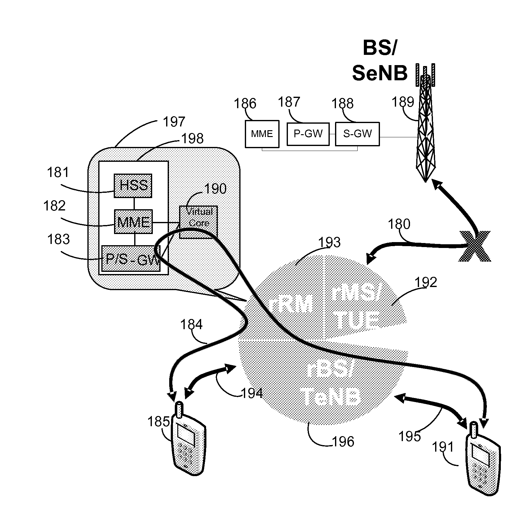
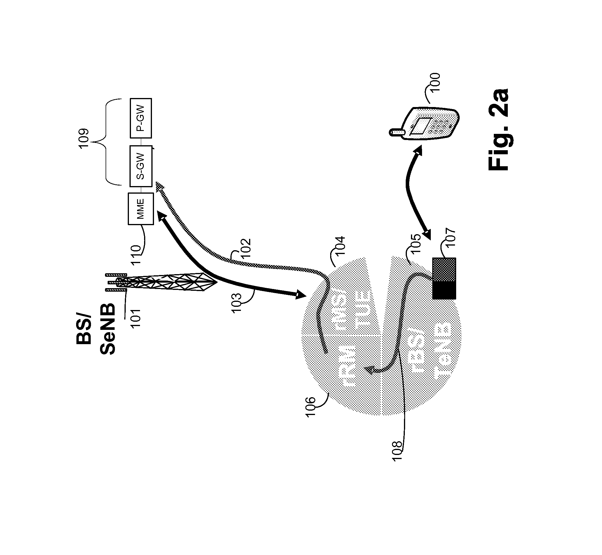
[0180]A moving cellular communication system comprising:

[0181]a plurality of moving relays each including base station functionality, a radio manager and mobile station functionality, all co-located,

[0182]wherein each base station functionality is operative to communicate via antennae with at least one mobile station thereby to define a first radio link there between, and wherein each base station functionality has a physical connection to its co-located radio manager,

[0183]wherein each mobile station functionality communicates via antennae with a unit which has base station functionality thereby to define a second radio link,

[0184]wherein the radio manager in each individual moving relay comprises:[0185]a radio resource manager; and[0186]functionality for exchanging information with radio managers included in moving relays other than said individual moving relay,

[0187]wherein said information is used by said radio resource manager to select, for at least one individual mobile stati...

embodiment 2

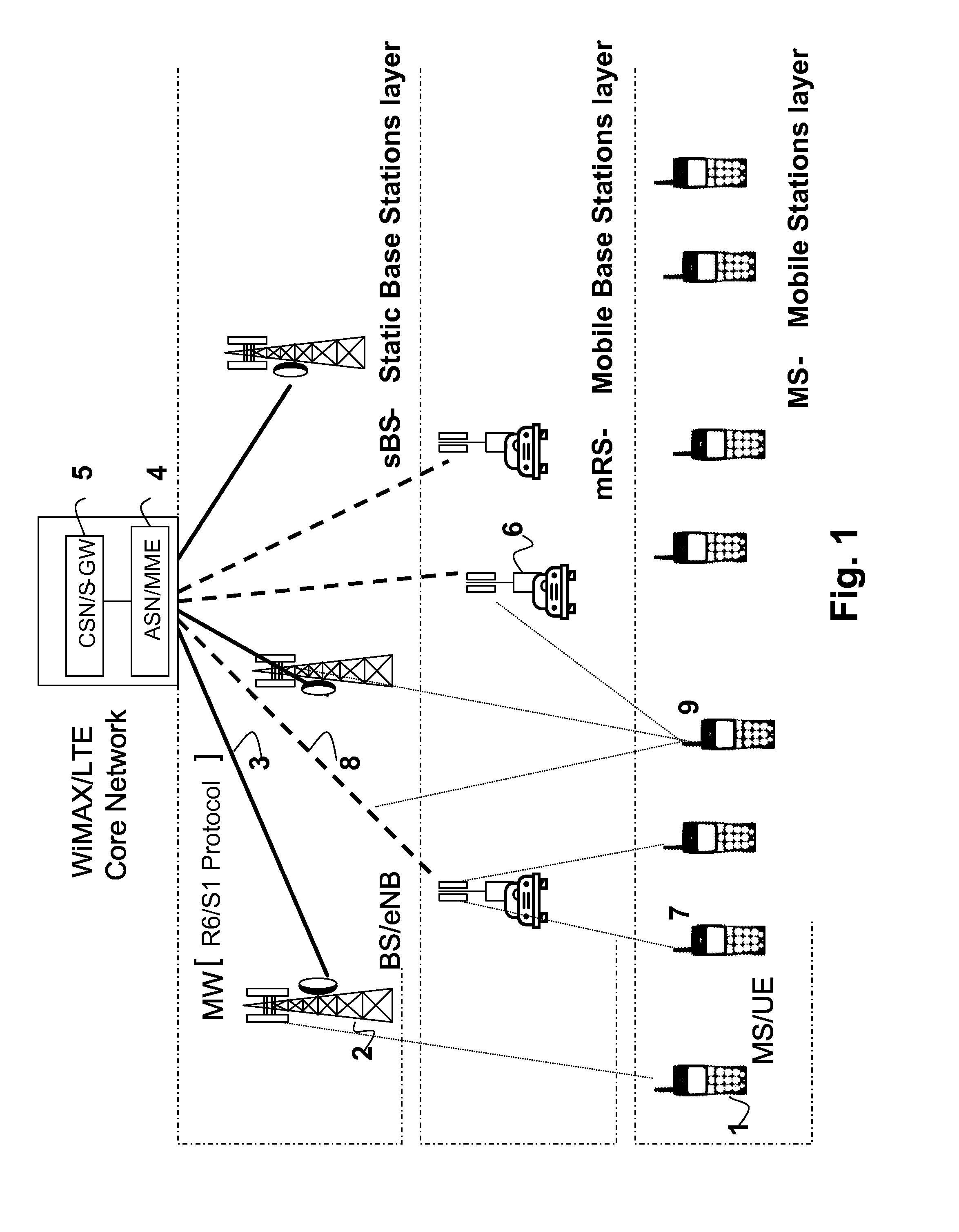
[0191]A system according to embodiment 1 operative in conjunction with a cellular network including a core device, at least one static base station, and a population of mobile stations communicating via antennae with at least one of the base stations, wherein at least one topological change in said system occurs dynamically, said topological change comprises a dynamic change in at least one connection between a moving relay and at least one of a moving relay and a static base station.

embodiment 3

[0192]A system according to embodiment 2 wherein at least one radio resource manager locally stores at least some of the information it uses to make a decision regarding selection of a cellular communication service provider for an individual mobile station seeking to be served, even after said decision has been made, thereby to generate a database co-located with said radio resource manager.


PUM


Abstract

A communication system comprising moving relay / s including base- and mobile-station functionality and a radio manager, all co-located, emergency moving relay / s further including a simulated stationary network that includes a simulated IP connectivity gateway communicating with a simulated mobility management entity and simulating the operation of a stationary network; the emergency moving relay being a root of a subtree including moving relay / s and mobile station / s, and utilizing its mobile-station functionality, base station functionality and radio manager for normal and emergency operation including communicating to a designated mobile station in the subtree each message received from a moving relay mobile in the subtree, the message having an IP address of the designated mobile station; or communicating to the simulated stationary network each message received from a moving relay / mobile station in the subtree and having an IP address not matching any mobile station in the subtree.

Description

REFERENCE TO CO-PENDING APPLICATIONS[0001]Priority is claimed from:[0002]U.S. Patent Application No. 61 / 451,344 “A moving cellular communication system operative in an emergency mode”, filed 10 Mar. 2011[0003]Israel Patent Application No. 218046, “A multi-directional relay architecture and apparatus and methods of operation useful in conjunction therewith”, filed 12 Feb. 2012.[0004]U.S. Patent Application No. 61 / 451,166 “Cellular communication system utilizing upgraded moving relays”[0005]U.S. Patent Application No. 61 / 451,339 “An IP based cellular communication system utilizing extended tunnels”.FIELD[0006]The field relates to architecture and data transmission methods for use in hierarchal cellular networks.BACKGROUND FOR THIS DISCLOSURE[0007]Multi-layer hierarchical dynamic cellular networks pose difficulties for traffic flow and management.[0008]A classical cellular network includes or consists of core segment and Radio Access Network (RAN). The core segment comprises at least a...

Claims


Application Information

Patent Timeline
Patent Type & Authority Applications(United States)
IPC IPC(8): H04W4/22H04W4/40H04W4/90H04W76/10H04W76/11H04W76/12
CPCH04W8/26H04W40/00H04W72/00H04W72/0453H04W80/04H04W84/005H04W84/047H04B7/15542H04B7/2606H04W76/10H04W4/90H04W76/12H04W8/085H04B7/1555H04J11/005H04J11/0056H04L1/0018H04W28/0215H04W28/0268H04W28/14H04W36/04H04W40/02H04W40/22H04W72/02H04W88/04H04W88/08H04W88/16H04L2212/00H04L61/2517H04W4/40H04W76/11H04W84/045H04W72/30H04W72/21H04W72/23H04W16/26H04W84/02
Inventor SCHWARTZ, ADISHOSHAN, YAAKOVSHERMAN, ITAYWEINSBERG, UDI
Owner ELTA SYST LTD
Why Eureka
Try Eureka