Can bus edge timing control apparatus, systems and methods

a timing control and can bus technology, applied in the field of data networking, can solve the problems of limiting the can bus bandwidth, the maximum number of attached nodes, the length of the can bus, etc., and achieves the effects of reducing the overall parallel bus impedance, increasing the decay rate, and modestly increasing the data ra

Active Publication Date: 2014-06-05
TEXAS INSTR INC
View PDF4 Cites 115 Cited by
  • Summary
  • Abstract
  • Description
  • Claims
  • Application Information

AI Technical Summary

Benefits of technology

[0024]Apparatus, systems and methods disclosed herein add additional bus impedance, referred to as “recessive nulling impedance,” in parallel across the CAN bus starting at a dominant-to-recessive bit transition. Doing so decreases overall parallel bus impedance to more quickly discharge residual charge stored in parasitic bus capacitance. CAN bus dominant-to-recessive waveform fall rates are increased (fall times shortened), permitting a decrease in CAN frame bit times in order to increase CAN bus bandwidth and throughput without sacrificing the integrity of the CAN bus arbitration mechanism.
[0026]FIG. 5 is a diagram illustrating a CAN bus differential waveform 500 resulting from various example embodiments and method activities while operating in LRN mode as described in detail below. During a recessive nulling time period [T(RN)]515, a transmitting CAN transceiver adds additional bus impedance across the CAN bus to decrease the overall parallel bus impedance. Doing so increases the rate of decay of the falling edge 520 of the bus waveform 500 during a dominant-to-recessive TxD bit transition. The transceiver releases the additional impedance from the bus at the end 525 of T(RN) 515 to avoid overloading the bus at the sampling time 440. Overloading the bus at the sampling time 440 could interfere with the arbitration process previously described during the arbitration bit times (e.g., the arbitration field 215 of FIG. 2) of the CAN data frame (e.g., the data frame 200 of FIG. 2). LRN may be applied during dominant-to-recessive bit transitions within the entire CAN frame including the arbitration field and may allow modest increases in data rates by decreasing the tbit period 435 of FIG. 4 to achieve a shortened tbit period 535.
[0027]FIG. 6 is a diagram illustrating a CAN bus differential waveform 600 affected by various example embodiments and method activities of the invention operating in HRN mode. During an HRN mode recessive nulling time period [T(RN)]610, a transmitting CAN transceiver adds additional bus impedance across the CAN bus beyond that added in LRN mode described above in conjunction with FIG. 5. Doing so decreases the overall parallel bus impedance and increases the rate of decay of the falling edge 615 of the bus waveform 600 beyond that described above for LRN mode. Also, unlike LRN mode, the transmitting CAN transceiver operating in HRN mode does not release the additional bus impedance during the recessive tbit period 635. This effectively extends the HRN mode T(RN) period 610 to the end 620 of the tbit period 635 or even to the end of successive recessive tbit periods 640.

Problems solved by technology

Such arbitration-time waveform shapes are frequency dependent in the presence of the above-described bus impedance considerations and ultimately limit CAN bus bandwidth, bus length, and the maximum number of attached nodes.

Method used


Image

  • Can bus edge timing control apparatus, systems and methods
  • Can bus edge timing control apparatus, systems and methods
  • Can bus edge timing control apparatus, systems and methods

Examples


Embodiment Construction

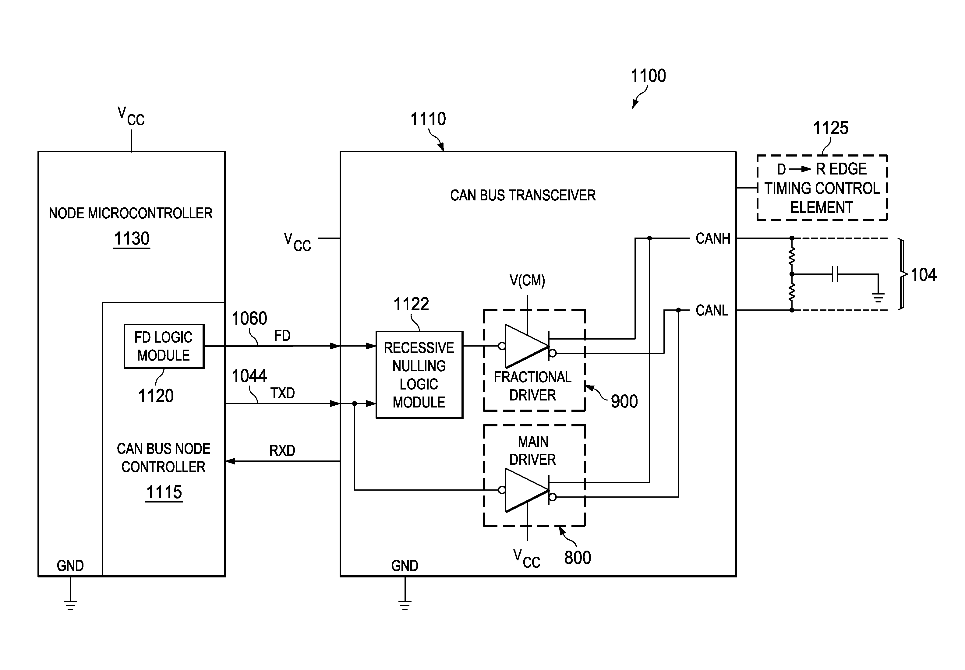
[0030]FIGS. 7A and 7B are a flow diagram illustrating a method 700 of CAN bus dominant-to-recessive transmit data bit timing control according to various example sequences. The method 700 commences at block 705 with selecting LRN mode, HRN mode, or mixed-mode for transmission of a CAN data frame.

[0031]The method 700 continues at block 710 with selecting the recessive nulling time period associated with LRN mode operation as a function of an expected bus impedance during a recessive bus state. The expected bus impedance is a function of one or more CAN bus characteristics including bus length, bus distributed parasitic capacitance, and bus loading contributed by a CAN node physical layer (PHY) driver. The recessive nulling time period is selected to drive the CAN bus differential waveform toward a recessive state at a chosen rate. The method 700 also includes, for HRN mode and for HRN portions of mixed-mode operation, selecting the recessive nulling time period to include at least on...


PUM


Abstract

Structures and methods herein insert one or more parallel “recessive nulling” driver impedances across a controller area network (CAN) bus starting at the time of a dominant-to-recessive data bit transition and extending for a selected recessive nulling time period. Doing so increases a rate of decay of a CAN bus dominant-to-recessive differential signal waveform, permits a shortened recessive bit time period, and allows for increased CAN bus bandwidth. Various modes of operation are applicable to various CAN bus node topologies. Recessive nulling may be applied to only the beginning portion of a recessive bit following a dominant bit (“LRN mode”) or to the entire recessive bit time (“HRN mode”). And, some embodiments may apply LRN operations to some recessive CAN frame bits and HRN operations to others.

Description

PRIORITY CLAIM[0001]This application claims the benefit of priority under 35 U.S.C. §119(e) to U.S. Provisional Patent Application Ser. No. 61 / 733,740 titled “Variable Dominant to Recessive Edge Timing Control For Improved Bit Timing In a CAN Physical Layer Implemented On Various Network Loads,” filed on Dec. 5, 2012 and incorporated herein by reference in its entirety.TECHNICAL FIELD[0002]Structures and methods described herein relate to data networking, including bus edge timing control in a controller area network (CAN).BACKGROUND INFORMATION[0003]A CAN is an International Standards Organization (ISO)-defined serial data communications bus topology and associated peer-to-peer message-based protocol. The CAN bus is used commercially in automotive, aerospace, maritime and a variety of industrial applications. Additional information regarding the CAN bus may be found in ISO 11898-1: 2003, “Road vehicles—Controller area network (CAN)—Part 1: Data link layer and physical signaling” (c...

Claims


Application Information

Patent Timeline
Patent Type & Authority Applications(United States)
IPC IPC(8): G06F13/372
CPCG06F13/4072H04L2012/40215H04L2012/40273G06F13/372G06F13/3625G06F13/364
Inventor MONROE, SCOTT ALLENSTOUT, DAVID WAYNE
Owner TEXAS INSTR INC
Why Eureka
Try Eureka