Systems and methods for remotely measuring a liquid level using time-domain reflectometry (TDR)

a technology of time-domain reflectometry and liquid level measurement, which is applied in the direction of liquid/fluent solid measurement, instruments, machines/engines, etc., can solve the problems of remote measurement of water level, discrimination methods of time-domain reflectometry (tdr), and no one can design to remotely measure water level, etc., to achieve the effect of maintaining the impedance characteristics, reducing seismic forces, and propagating pulse tdr signals

Active Publication Date: 2014-06-12
GE HITACHI NUCLEAR ENERGY AMERICAS
View PDF7 Cites 27 Cited by
  • Summary
  • Abstract
  • Description
  • Claims
  • Application Information

AI Technical Summary

Benefits of technology

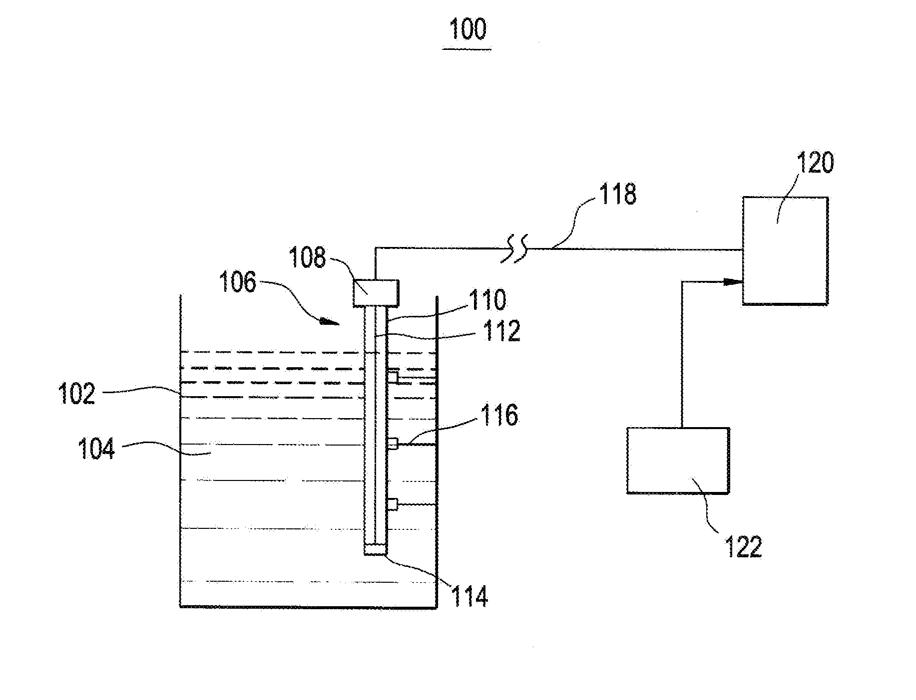
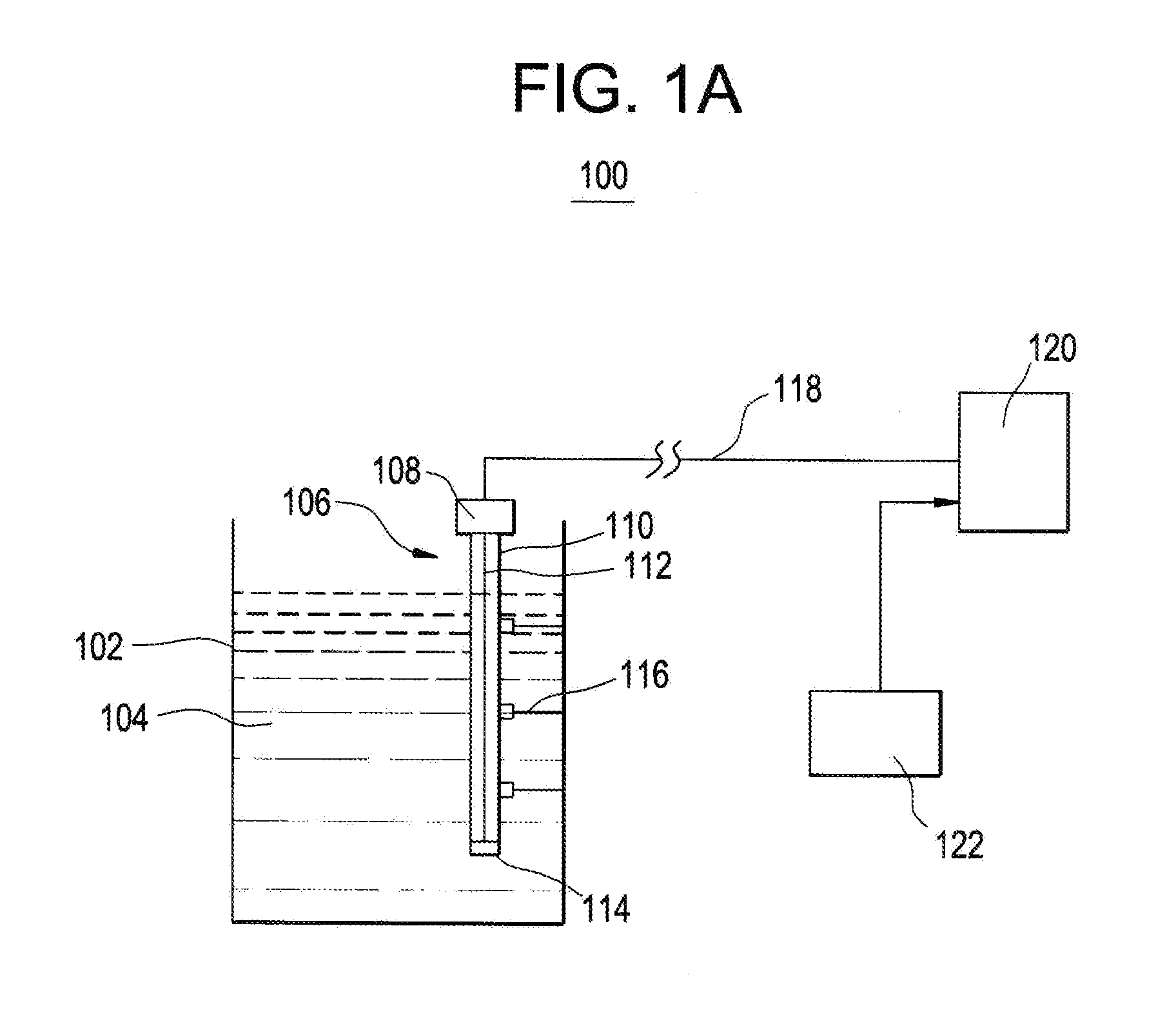
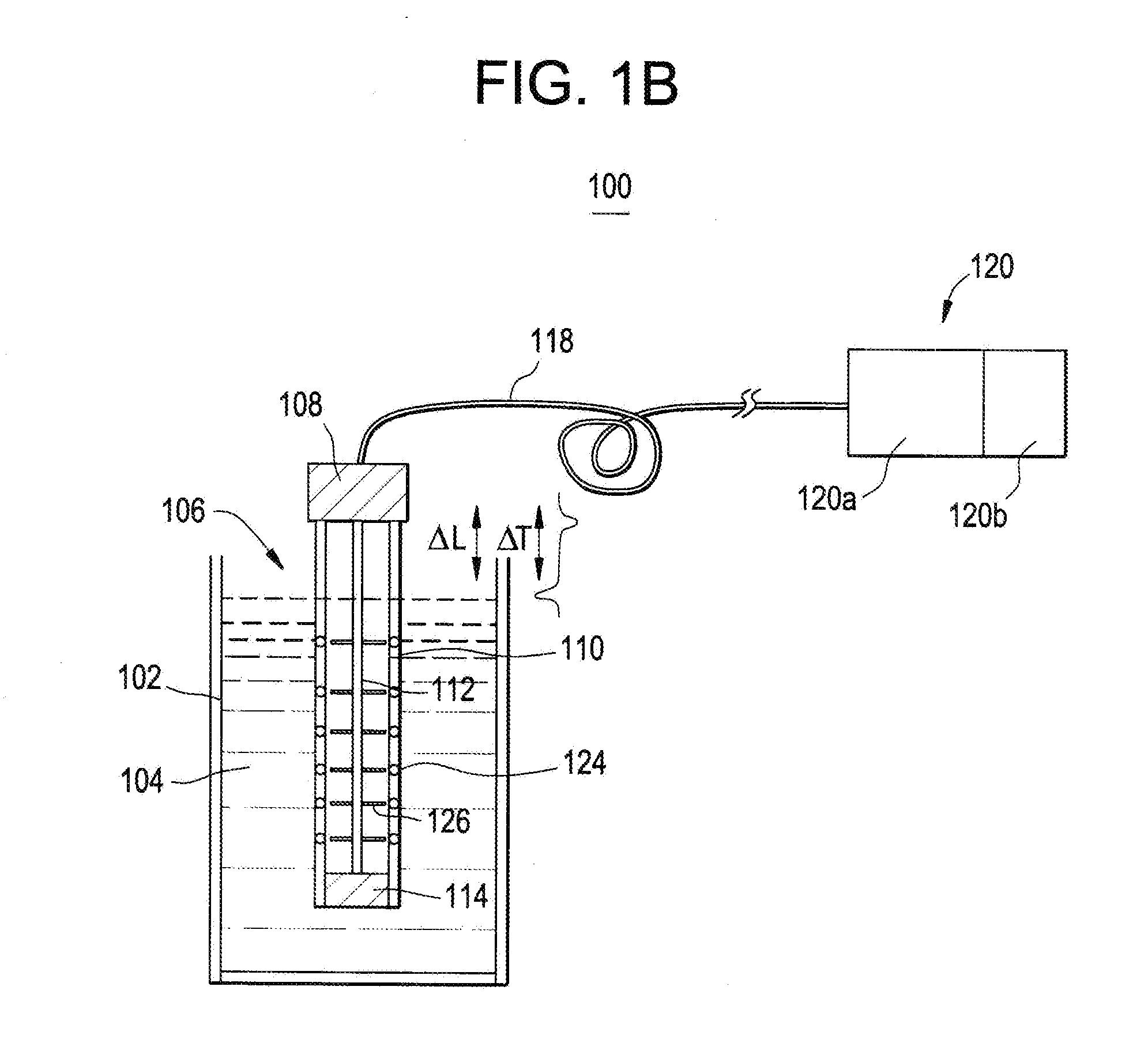
[0017]The probe is designed in a coaxial transmission line configuration with an inner rod within an outer tube, and probe length equal to or more than the length of the water level that is to be measured (˜35 ft. for the SFP application). To assure that the impedance characteristics are maintained throughout the length of the probe, the design provides thin insulating spacers located every 5 ft. between the inner and outer electrodes that assure that the geometry of the gap (or concentricity) between the probe inner and outer electrodes remains constant throughout the length of the probe. The probe top has a coaxial head connector which mates to the coaxial cable, and designed with a small axial length (e.g., few inches) so that it does not introduce an interfering reflected impedance mismatch pulse, and provides an effective seal between the inside and outside of the probe. The probe bottom has a plate that welds the center and outer electrodes which provides a solid probe design, and the impedance mismatch pulse from the bottom does not interfere with the water level measurement since it occurs later than the impedance mismatch Pulse #2 from the probe air / water interface.
[0018]The probe electrodes are fabricated with conducting metals (such as stainless steel) that propagate pulse TDR signals effectively and also make rugged probes capable of operating in hostile post-accident radiation, temperature, seismic and water quality environment. Conductive coatings using material such as gold can be put on the electrodes if necessary. The insulating spacers are made of materials that can be fabricated to meet the spacer design and to withstand high radiation, temperature and water quality environment (such as zirconium, ceramic, quartz) inside the probe. The insulator between the electrode connections in the probe top connector is made of a material that can be fabricated to meet the connecter design and to withstand high radiation and temperature environment in the probe above the SFP water.
[0019]The probe outer tube has holes in it throughout the length of the probe and in the bottom plate to allow water to move freely in the probe and to ensure that the water level inside the probe is the same as the water level outside the probe. The insulating spacers are also designed to allow water to move freely through and around them.
[0020]The probe may be installed in the SFP using a unique ball and socket design where the ball is welded to the probe and the socket is integral to a plate that is welded to SFP liner curb or anchored to the Refuel Floor. The probe hangs like a pendulum with the ball sitting in the socket. In a seismic event the probe would swing like a pendulum damped by the SFP water and restrained by the wall of the SFP. The low natural frequency reduces the seismic forces on the probe and simplifies its qualification to specified seismic spectra. The mounted probe assembly is fitted with a cover to protect it during normal and post-accident environment. The cover may also house the calibration cable and provide protection for the calibration cable and probe connector.
[0021]The probe and its mounting in the SFP are designed to allow for simple in-situ probe calibration. This in-situ calibration may be accomplished by simply raising and lowering the probe vertically in the SFP by means of a lifting ring (or hook) attached to the top of the probe, and measuring the corresponding change in water level relative to the top of the probe. The probe can be moved vertically by an amount equal to the length of the calibration cable (˜6 ft.), and that may be all that is needed for the probe calibration. No removal of the probe from the SFP, or complicated means of raising and lowering the water in the probe, is required for probe calibration.

Problems solved by technology

Although there are time-domain reflectometry (TDR) based water level measurement systems, none are designed to remotely measure water levels (e.g., spent fuel pool (SFP) water levels) from relatively far distances by utilizing impulses and relatively highly specialized time-domain reflectometry (TDR) discrimination methods.
However, all such conventional techniques require electronics in the vicinity (i.e., relatively close proximity) of the spent fuel pool (SFP) and, thus, are not suitable for water level measurement in a hostile post-accident environment which could include high radiation, high temperatures, high seismic activity, fire, explosions, and falling debris.
Any small change in velocity could cause a significant error in water level because of the long length (e.g., 1000 ft.) of the cable.
This arrangement with the calibration cable effectively lengthens the distance from the top of the probe to the water level from the pulse timing point of view, since it allows the first reflection impedance mismatch Pulse #1 to occur at the interface between the calibration cable and the 1000 ft. cable and does not provide an impedance mismatch pulse at the probe top.
The use of a short calibration cable can also facilitate probe vertical movement and calibration, since the long coaxial cable transmission line may be fixed in a conduit and not able to move easily.

Method used


Image

  • Systems and methods for remotely measuring a liquid level using time-domain reflectometry (TDR)
  • Systems and methods for remotely measuring a liquid level using time-domain reflectometry (TDR)
  • Systems and methods for remotely measuring a liquid level using time-domain reflectometry (TDR)

Examples


Embodiment Construction

[0033]It should be understood that when an element or layer is referred to as being “on,”“connected to,”“coupled to,” or “covering” another element or layer, it may be directly on, connected to, coupled to, or covering the other element or layer or intervening elements or layers may be present. In contrast, when an element is referred to as being “directly on,”“directly connected to,” or “directly coupled to” another element or layer, there are no intervening elements or layers present. Like numbers refer to like elements throughout the specification. As used herein, the term “and / or” includes any and all combinations of one or more of the associated listed items.

[0034]It should be understood that, although the terms first, second, third, etc. may be used herein to describe various elements, components, regions, layers and / or sections, these elements, components, regions, layers, and / or sections should not be limited by these terms. These terms are only used to distinguish one eleme...


PUM


Abstract

A remote pulse TDR liquid level measurement system and method may include inserting a probe into a body of water. The probe has a probe/air interface, and the body of water includes an air/water interface. A narrow pulse is remotely transmitted to the probe via a coaxial cable. A first impedance mismatch is received from the probe/air interface in a form of a positive reflected pulse, and a second impedance mismatch is received from the air/water interface in a form of a negative reflected pulse. A time between the positive reflected pulse and the negative reflected pulse is calculated, and the time is converted to a distance, the distance being indicative of the water level.

Description

BACKGROUND[0001]1. Field[0002]The present disclosure relates to systems and methods for measuring a liquid level.[0003]2. Description of Related Art[0004]Conventionally, time-domain reflectometry (TDR) has been used to characterize and locate faults in metallic cables. Although there are time-domain reflectometry (TDR) based water level measurement systems, none are designed to remotely measure water levels (e.g., spent fuel pool (SFP) water levels) from relatively far distances by utilizing impulses and relatively highly specialized time-domain reflectometry (TDR) discrimination methods. For instance, one conventional time-domain reflectometry (TDR) system utilizes a step wave rather than impulse. Other conventional approaches include guided wave radar (GWR) techniques which use technology in this general category. However, all such conventional techniques require electronics in the vicinity (i.e., relatively close proximity) of the spent fuel pool (SFP) and, thus, are not suitable...

Claims


Application Information

Patent Timeline
Patent Type & Authority Applications(United States)
IPC IPC(8): G01F23/00
CPCG01F23/00G01F23/284G01R27/02G01R27/26G01R27/2605G01F23/26
Inventor DAYAL, YOGESHWARSPLICHAL, WILLIAM FRANCISSAWYER, STEVEN D.GARDNER, ERIC RANKINLENTNER, BRUCE J.EISERMANN, PHILIP O.
Owner GE HITACHI NUCLEAR ENERGY AMERICAS
Why Eureka
Try Eureka