Transmitter, signal synthesis circuit, and signal synthesis method

a signal synthesis circuit and signal synthesis technology, applied in the direction of amplifiers, dual/triple band amplifiers, semiconductor devices/discharge tubes, etc., can solve the problems of large loss of variable inductance, large size of signal synthesis circuit, and difficulty in achieving a downsized signal synthesis circuit compatible with a plurality of transmission frequencies. achieve the effect of maintaining impedance characteristics and not increasing circuit siz

Active Publication Date: 2017-11-02
NEC CORP
View PDF2 Cites 8 Cited by
  • Summary
  • Abstract
  • Description
  • Claims
  • Application Information

AI Technical Summary

Benefits of technology

[0037]A transmitter, a signal-synthesizing circuit, and a signal-synthesizing method according to the present invention can provide the following advantageous effects.
[0038]In other words, the transmitter according to the present invention includes at least: a modulation circuit configured to modulate a baseband signal into a multi-bit digital signal including a component in a radio frequency band; a switch-mode amplifier configured to amplify the multi-bit digital signal output from the modulation circuit for each bit; a frequency-variable band-limiting unit configured to band-limit each of output signals from the switch-mode amplifier; a voltage / current source conversion unit configured to perform voltage-to-current conversion of each of output signals from the band-limiting unit; a synthesizing point configured to synthesize output signals from the voltage / current source conversion unit; and an impedance correction unit disposed on a signal path between the synthesizing point and an antenna serving as a load and configured to correct an impedance. Since the configuration in which a variable part is limited only to a variable capacitance part is employed, it is possible to synthesize the output signals (multi-bit digital transmission signals) from a plurality of switch-mode amplifiers while maintaining impedance characteristics with respect to a plurality of transmission frequencies, and to transmit the synthesized signal as a transmission signal, without increasing a circuit size.

Problems solved by technology

However, there is a problem that a circuit size increases as the number of transmission frequency bands increases, which makes it difficult to achieve a downsized signal-synthesizing circuit compatible with a plurality of transmission frequencies.
However, in the case of the signal-synthesizing circuit as illustrated in FIG. 9, when the number of syntheses of the power amplifier (PA) is represented by N and the number of transmission frequency bands is represented by M, (N×M) ¼ wavelength transmission lines are required, which causes a problem that a size of the signal-synthesizing circuit increases along with an increase in the number of syntheses and the number of bands.
However, in general, the variable inductor has a large loss, which makes it difficult to adapt the variable inductor to a power amplifier filter and a signal-synthesizing circuit which are required to have a low Q-value (Quality factor) and high efficiency.
This causes a problem that, when only the variable capacitance is adapted to the signal-synthesizing circuit illustrated in the above-mentioned PTL1, an impedance characteristic of the signal-synthesizing circuit fluctuates with respect to a plurality of frequencies and output power also fluctuates in accordance with the fluctuation.

Method used


Image

  • Transmitter, signal synthesis circuit, and signal synthesis method
  • Transmitter, signal synthesis circuit, and signal synthesis method
  • Transmitter, signal synthesis circuit, and signal synthesis method

Examples


example embodiments

Configuration Example of Example Embodiments

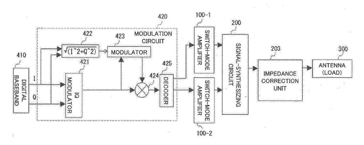
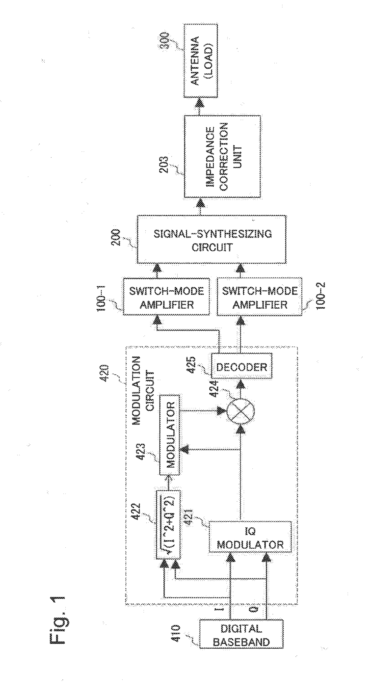
[0061]A configuration example of a transmitter according to an example embodiment of the present invention will be described in detail with reference to FIG. 1. FIG. 1 is a block diagram illustrating an example of the overall configuration of the transmitter according to an example embodiment of the present invention. As illustrated in FIG. 1, the transmitter according to the present example embodiment includes at least a digital baseband (DBB; hereinafter abbreviated as DBB) signal generation unit 410, a modulation circuit 420, switch-mode amplifiers 100-1 and 100-2, a signal-synthesizing circuit 200, an impedance correction unit 203, and an antenna (load) 300. Note that the present example embodiment illustrates a case where the impedance correction unit 203 is disposed at a subsequent stage of the signal-synthesizing circuit 200 separately from the signal-synthesizing circuit 200. However, in some cases, the impedance correction unit 20...


PUM


Abstract

A multi-bit digital signal that is generated by modulating a baseband signal by a modulation circuit and includes components in a radio frequency band is amplified by switch-mode amplifiers (100-1, 100-2) on a bit-by-bit basis, amplified signals are band-limited by frequency-variable variable band limiting units (201-1, 201-2) and thereafter subjected to voltage-to-current conversion by voltage/current source conversion units (202-1, 202-2) provided with variable capacitances, the signals converted to current are synthesized at a synthesis point X, and a resultant signal is impedance-corrected by an impedance correction unit (203) and output as a transmission signal to an antenna of a load (300). Consequently, the present invention provides a transmitter capable of synthesizing output signals from a plurality of switch-mode amplifiers and transmitting a resultant signal while maintaining an impedance characteristic with respect to a plurality of transmit frequencies without increasing a circuit size.

Description

TECHNICAL FIELD[0001]The present invention relates to a transmitter, a signal-synthesizing circuit, and a signal-synthesizing method, and more particularly, to a transmitter, a signal-synthesizing circuit, and a signal-synthesizing method that are capable of synthesizing signals of a plurality of radio frequencies. The present invention can be suitably applied as, for example, a transmitter that synthesizes output signals obtained by amplifying a multi-bit digital signal including a radio frequency band component by a plurality of switch-mode amplifiers and transmits the synthesized signal.BACKGROUND ART[0002]A base station of a wireless communication system transmits a signal with a large difference between average power and peak power. In recent years, a digital transmitter that converts a baseband signal to be transmitted into a digital transmission signal including a radio frequency band component and amplifies the signal has been studied as a technique for improving efficiency ...

Claims


Application Information

Patent Timeline
Patent Type & Authority Applications(United States)
IPC IPC(8): H04B1/04H03F3/24
CPCH04B1/04H03F2200/387H03F2200/336H03F3/245H03F1/565H03F3/211H03F3/2173H03F3/2178H03F3/604H03H7/0153H03H7/09H03H7/175H03H7/38H03F2200/111H03H7/1775H04B1/0458H04B1/0475H04B1/0003H04B1/0483H04B2001/0408
Inventor MOTOI, KEIICHI
Owner NEC CORP
Why Eureka
Try Eureka