

Method for surface decoration of an object with 3-dimensional geometry and the object obtained therefrom
- Summary
- Abstract
- Description
- Claims
- Application Information
AI Technical Summary
Benefits of technology
Problems solved by technology
Method used
Image

Examples
first embodiment
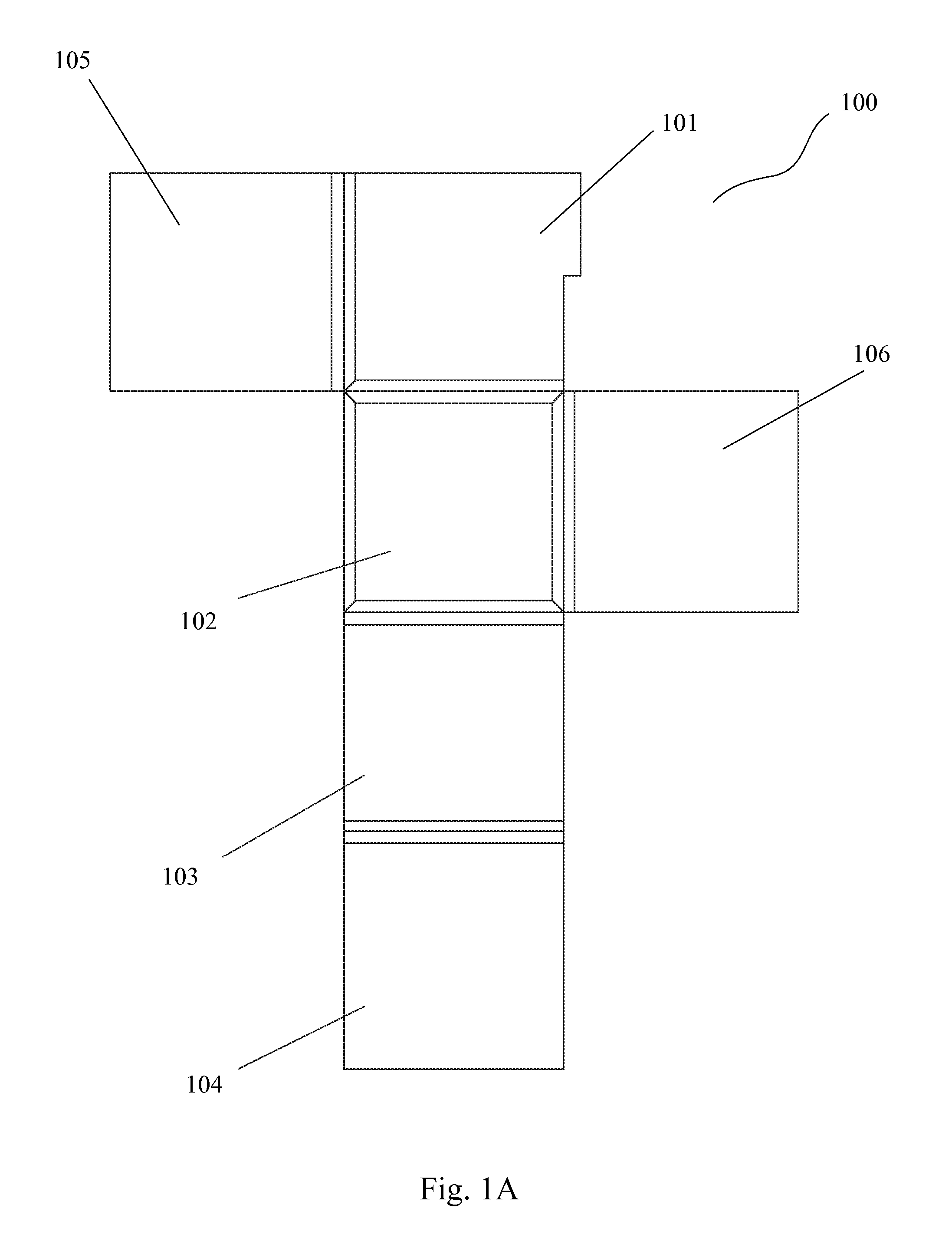
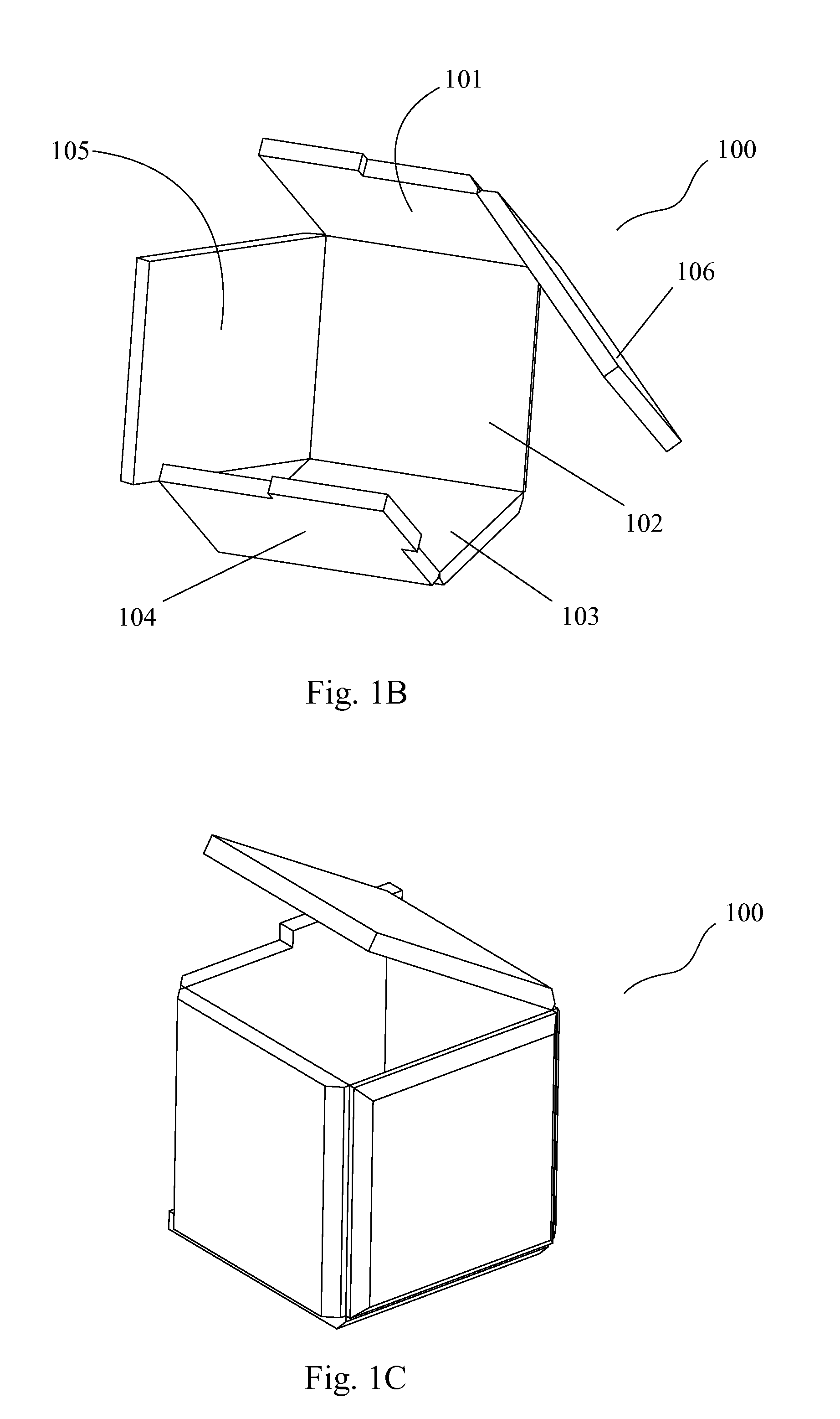
[0061]Referring now to the drawings, FIGS. 1A to 1C provide a foldable article 100 having the basic planar construction constructed consistent with the present invention. In this embodiment, the planar construction article 100 comprises first to fourth section areas 101, 102, 103, 104 aligned together, fifth section area 105 extending from and perpendicular to the first section area 101, and sixth section area 106 extending from and perpendicular to the second section area 102. All the six section areas are in the substantially same planar plane, and each two adjacent section areas have a fold line or a hinge along which they can be folded up. The six section areas 101-106 together may be easily folded up to construct a cube, with the section areas 101-106 configured as the respective faces of the cube, as shown in FIGS. 1B and 1C.
[0062]The planar construction article 100 is basically flat in its unfolded position, and all the section areas are in the same plane before they are fold...
second embodiment
[0076]Of course, like the second embodiment described above, an extra panel (not shown) may be diagonally provided inside the cube to carry an electronic assembly or component for facilitating and allowing the conductive connection of the assembly or component with each of the electroplated L-shaped panels, if needed.
[0077]FIG. 11 illustrates an exemplary means for constraining the L-shaped panels to retain the three-dimensional geometry. In this embodiment, a cubic frame 500 is provided with each cube face being hollowed out to expose the surfaces of the side panels of the L-shaped panels, which surfaces are configurable as the cube faces when the panels are constrained. The cubic frame 500 is usually non-conductive, so each two panels would not be able to form conductive connection through the frame 500. This cubic frame 500 are formed with a plurality of snap-fittable female or male joints 501 which are able to create interlocked joints with the male or female joints 307 of the r...
PUM
| Property | Measurement | Unit |
|---|---|---|
| Time | aaaaa | aaaaa |
| Electrical conductivity | aaaaa | aaaaa |
| Flexibility | aaaaa | aaaaa |
Abstract
Description
Claims
Application Information