

Roughing and Semi-Finishing End Mill Having Serrated and Non-Serrated Cutting Teeth
a technology of cutting teeth and end mills, which is applied in the field of end mills to achieve the effects of reducing chatter, cost-effectiveness, and increasing chatter
- Summary
- Abstract
- Description
- Claims
- Application Information
AI Technical Summary
Benefits of technology
Problems solved by technology
Method used
Image

Examples
Embodiment Construction
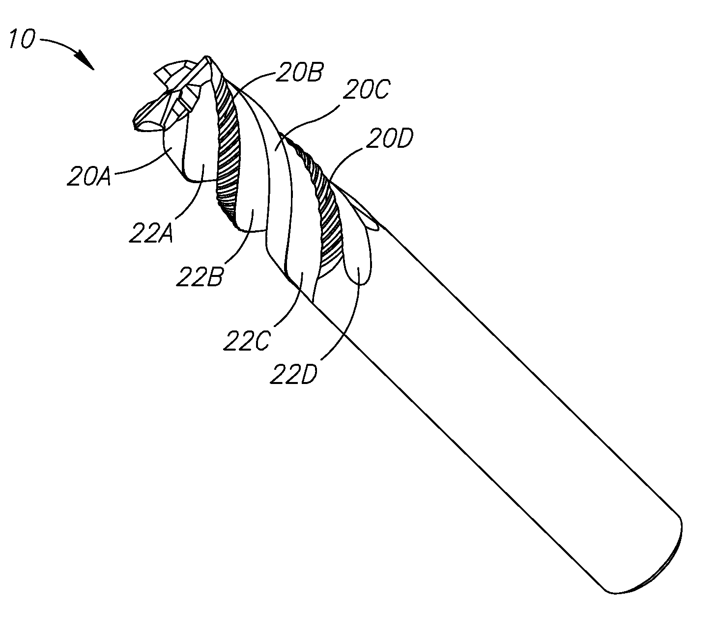
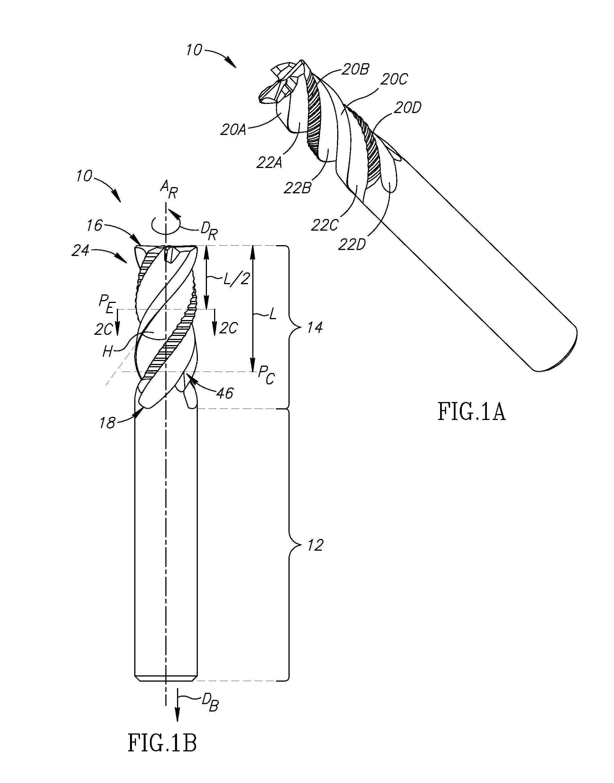
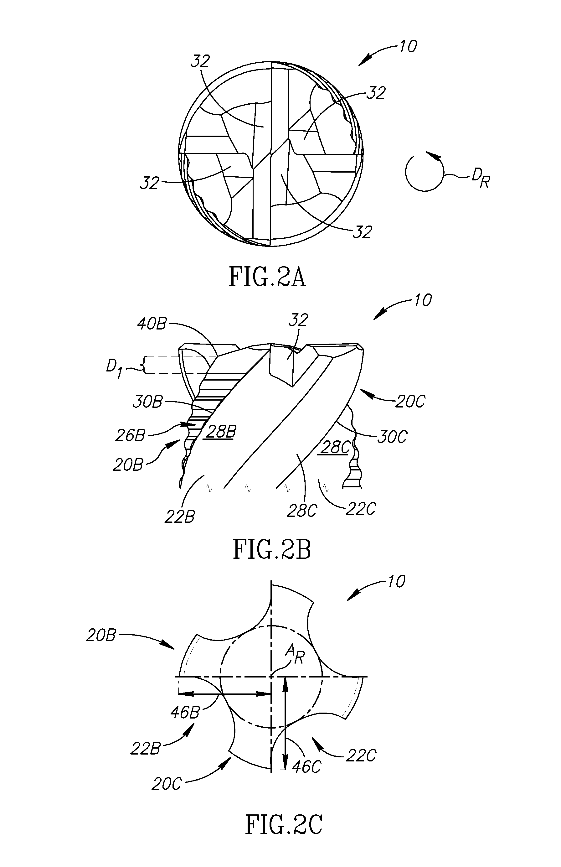
[0045]Reference is made to FIGS. 1A and 1B, which illustrate a roughing and semi-finishing end mill 10, typically made of extremely hard and wear-resistant material such as cemented carbide, configured to rotate about a rotation axis (AR) extending longitudinally through the center thereof in a counter-clockwise direction DR in the view shown in FIG. 2A.
[0046]The end mill 10 comprises a shank portion 12 and a cutting portion 14 extending therefrom.
[0047]More precisely, the cutting portion 14 extends along the rotation axis AR in a rearward axial direction DB from a cutting end face 16 to a furthermost flute end 18.
[0048]The cutting portion 14 is integrally formed with at least one cutting tooth 20A, 20B, 20C, 20D and at least one flute 22A, 22B, 22C, 22D.
[0049]The flutes 22A, 22B, 22C, 22D can be helical flutes. The flutes can all have the same constant helix angle H. In this non-limiting example, the helix angle H is about 45°, which has been found to be an effective value when mac...
PUM
 Abstract
Description
Claims
Application Information