On-chip controller and a system-on-chip

Active Publication Date: 2014-06-12
SAMSUNG ELECTRONICS CO LTD
View PDF2 Cites 15 Cited by
  • Summary
  • Abstract
  • Description
  • Claims
  • Application Information

AI Technical Summary

Benefits of technology

[0009]Exemplary embodiments of the inventive concept provide an on-chip clock controller capable of r

Problems solved by technology

This is so, because as circuit geometry is reduced and threshold voltages become lower, the reliability of a digital integrated circuit (IC) can be adversely a

Method used


Image

  • On-chip controller and a system-on-chip
  • On-chip controller and a system-on-chip
  • On-chip controller and a system-on-chip

Examples


Example

[0035]Exemplary embodiments of the inventive concept will be described more fully hereinafter with reference to the accompanying drawings. The present inventive concept may, however, be embodied in many different forms and should not be construed as limited to the exemplary embodiments set forth herein. In the drawings, the sizes of elements may be exaggerated for clarity.

[0036]It will be understood that when an element is referred to as being “on,”“connected to” or “coupled to” another element, it can be directly on, connected or coupled to the other element or intervening elements may be present. Like reference numerals may refer to like elements throughout this application.

[0037]As used herein, the singular forms “a,”“an” and “the” are intended to include the plural focus as well, unless the context clearly indicates otherwise.

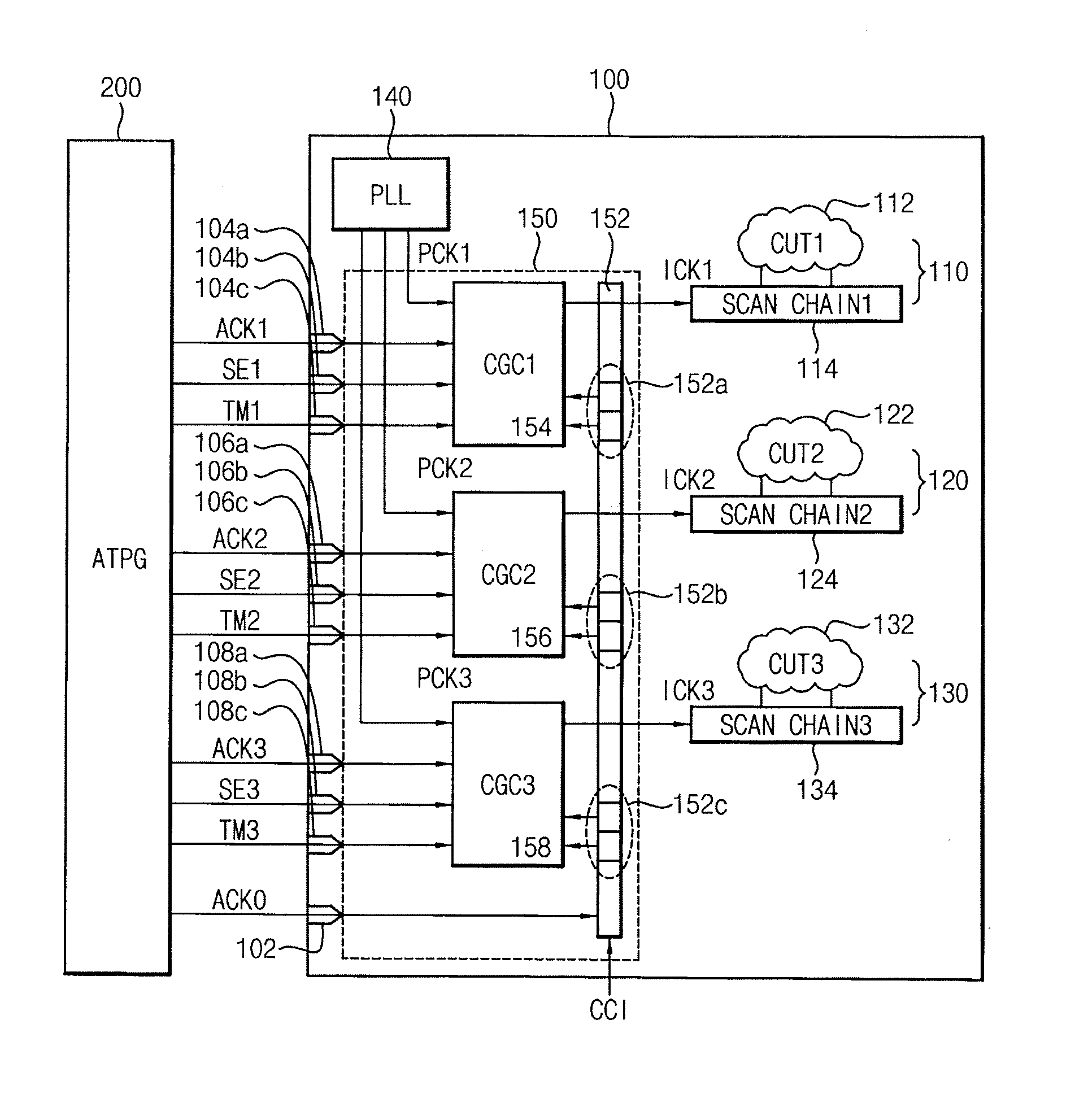
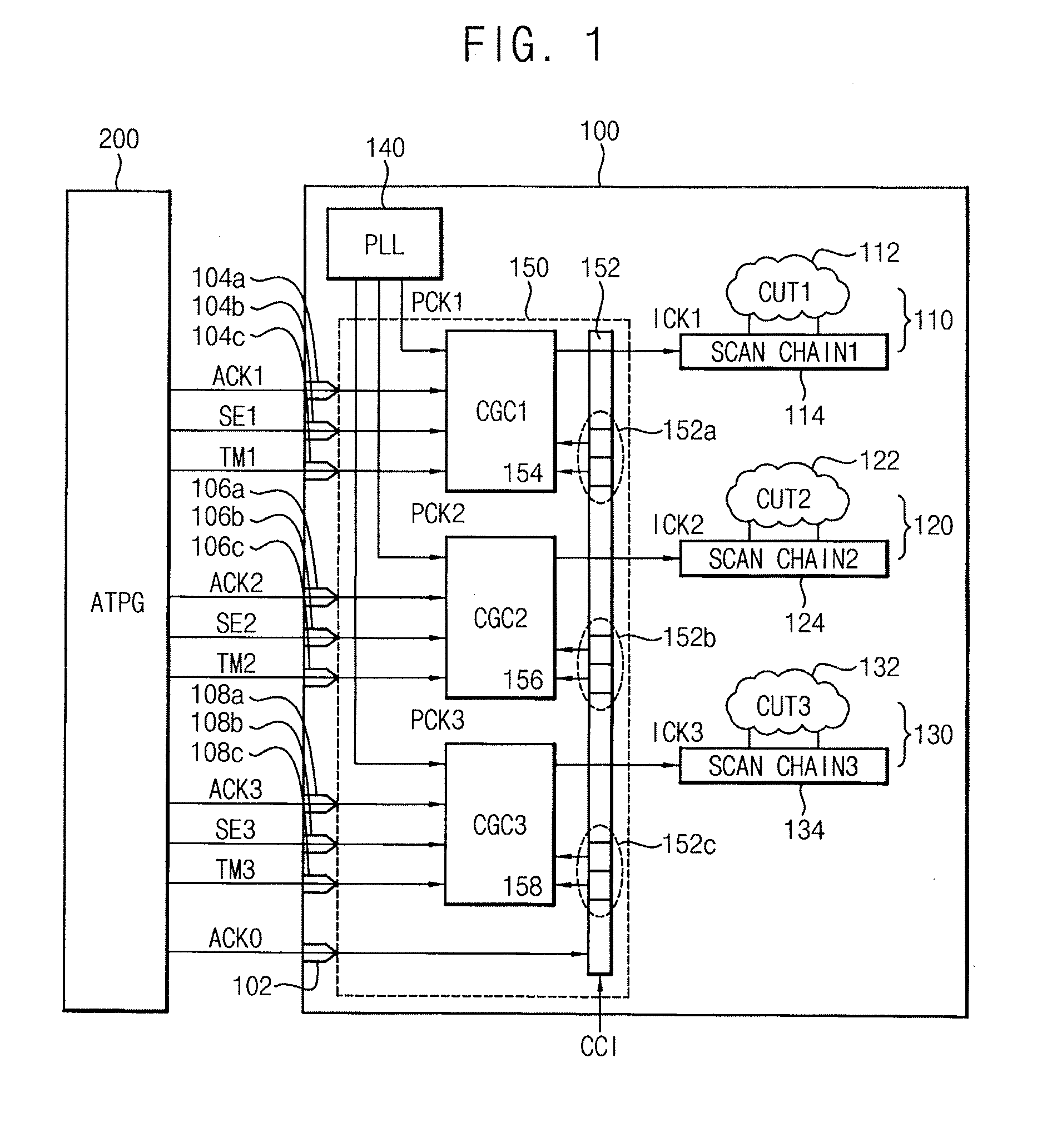
[0038]FIG. 1 is a block diagram illustrating a system-on-chip (SOC) having an at-speed test function according to an exemplary embodiment of the inventive ...


PUM


Abstract

An on-chip clock controller includes a clock-control chain configured to shift first clock-control bits in serial and output the first clock-control bits to a first clock domain in parallel in response to a clock-control scan clock provided from outside of a chip, and a first domain clock generator, the first domain clock generator configured, during a test mode, to generate a first internal clock by selectively outputting a first data scan clock provided from outside of the chip or a first functional clock generated from inside of the chip.

Description

CROSS-REFERENCE TO RELATED APPLICATION[0001]This U.S. non-provisional patent application claims priority under 35 U.S.C. §119 to Korean Patent Application No. 10-2012-0144197 filed on Dec. 12, 2012 in the Korean Intellectual Property Office (KIPO), the disclosure of which is incorporated by reference herein in its entirety.BACKGROUND[0002]1. Technical Field[0003]The inventive concept relates to electronic devices. More particularly, the inventive concept relates to on-chip clock controllers and system-on-chips (SOCs).[0004]2. Discussion of the Related Art[0005]An at-speed test may be used to detect a transition delay fault as well as a stuck-at fault in a system-on-chip (SOC) or other electronic devices. The at-speed test may apply a high-speed clock used for normal operation to capture data with a real operating frequency while simultaneously performing a scan operation using a slow scan clock in a scan mode.[0006]For the at-speed test, an on-chip clock controller (OCCC) of a SOC m...

Claims


Application Information

Patent Timeline
IPC IPC(8): G01R31/317
CPCG01R31/31727G01R31/318536G01R31/318552G01R31/318555G01R31/28G06F1/04
Inventor KIM, DAE-WOONG
Owner SAMSUNG ELECTRONICS CO LTD
Why Eureka
Try Eureka