Spectrometer

a spectrometer and light source technology, applied in the field of spectrometers, can solve the problems of reducing the measurement accuracy of the spectral characteristics in the short wavelength range received by the photo-diode, affecting the accuracy of the the difficulty in performing accurate measurement of the spectral characteristics of the incident light, so as to achieve the effect of high-quality spectral characteristics measurement and raising the accuracy of spectral characteristics

Active Publication Date: 2014-06-19
SEIKO EPSON CORP
View PDF4 Cites 44 Cited by
  • Summary
  • Abstract
  • Description
  • Claims
  • Application Information

AI Technical Summary

Benefits of technology

The invention provides a spectrometer with high accuracy for measuring spectral characteristics. It includes two light sources, one with a peak wavelength in the range of visible light and a light amount increasing as the wavelength gets longer, and the other with a peak wavelength within the range of visible light. The two light sources are mixed using a light mixer, and the resulting mixture is received by a light receiving unit. The measurement control unit measures the spectral characteristics of the target light transmitted by a wavelength variable interference filter. Even when only the first light source is used, which has no peak wavelength in the range of visible light, the second light source can still compensate for the light amount in a specific range. This improves the measurement accuracy and enables highly accurate spectral characteristics measurement.

Problems solved by technology

Thus, the light amount in the short wavelength range received by the photo-diode further decreases, which lowers the measurement accuracy of the spectral characteristics in the short wavelength range and thus makes it difficult to perform accurate measurement of the spectral characteristics of the incident light.

Method used


Image

  • Spectrometer
  • Spectrometer
  • Spectrometer

Examples


first embodiment

[0024]A first embodiment according to the invention is hereinafter described with reference to the drawings.

1. General Structure of Spectrometer

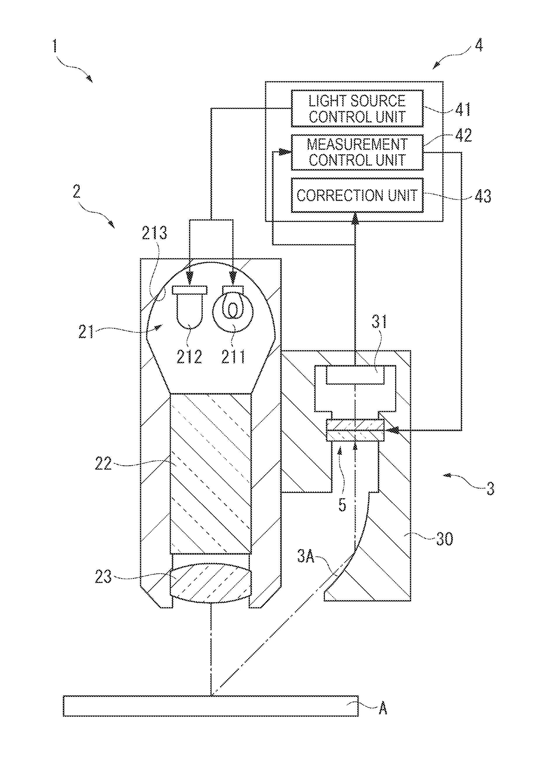
[0025]FIG. 1 illustrates the general structure of a spectrometer 1 according to the first embodiment.

[0026]As illustrated in FIG. 1, the spectrometer 1 includes a light source device 2 which emits light toward a test target A, a dividing device 3 which has an etalon 5 (e.g., wavelength variable range: 380 nm to 780 nm) for dividing test target light reflected by the test target A, and a control device 4 which controls the overall operation of the spectrometer 1. The spectrometer 1 is a system which divides test target light emitted from the light source device 2 and reflected by the test target A by using the dividing device 3, and measures the respective amounts of divided light having different wavelengths based on detection signals outputted from the dividing device 3.

[0027]The spectrometer 1 is also a system which only turns on a violet ...

second embodiment

[0063]FIG. 7 illustrates the general structure of a spectrometer 1A in a second embodiment.

[0064]According to the first embodiment, the light source unit 21 includes a pair of light sources constituted by the tungsten lamp 211 and the violet LED 212. In this embodiment, however, a light source unit 21A includes a blue LED 214 and a green LED 215 in addition to the light sources 211 and 212 as four light sources 211, 212, 214, and 215.

[0065]FIG. 8 is a graph showing the spectral distribution of light emitted from the light source unit 21A in this embodiment.

[0066]The blue LED 214 has the spectral distribution indicated by a solid line L1 in FIG. 8. As shown in the figure, the blue LED 214 has a spectral distribution within the range from about 420 nm to about 525 nm, and has a peak wavelength at 470 nm where the light amount becomes maximized.

[0067]The green LED 215 has the spectral distribution indicated by a solid line L2 in FIG. 8. As shown in the figure, the green LED 215 has a s...

embodiment

Modifications of Embodiment

[0077]The invention is not limited to the embodiments described herein but may be practiced otherwise without departing from the scope of the invention. Thus, modifications, improvements and the like including the following changes can be made.

[0078]According to the respective embodiments, a second light source is constituted by the violet LED 212. However, the second light source may be other light sources as long as they have a peak wavelength within the wavelength range from about 385 nm to about 450 nm. For example, the second light source may be an ultraviolet LED whose peak wavelength is 385 nm. In this case, the spectral distribution shown in FIG. 10 is produced as light which can effectively compensate for the light amount around 400 nm where the light amount emitted from the tungsten lamp 211 is small.

[0079]According to the respective embodiments, the structure of the etalon 5 whose gap G between the mirrors can be controlled by using the electros...


PUM

PropertyMeasurementUnit
wavelengthaaaaaaaaaa

Abstract

A spectrometer includes: a tungsten lamp which emits light with no peak wavelength within a wavelength range of visible light and having a light amount increasing as the wavelength becomes longer; a violet LED which emits light having a peak wavelength within the wavelength range of visible light; a light mixer which mixes light emitted from the tungsten lamp and the violet LED; an etalon which receives light mixed by the light mixer and transmits light contained in the received mixed light and having a particular wavelength; a light receiving unit which receives light transmitted by the etalon; and a measurement control unit which changes the wavelength of light that can pass through the etalon and measures spectral characteristics of the light having passed through the etalon based on the light received by the light receiving unit.

Description

[0001]This is a continuation patent application of U.S. application Ser. No. 13 / 227,758 filed Sep. 8, 2011, which claims priority to Japanese Patent Application No. 2010-262758 filed Nov. 25, 2010 all of which are expressly incorporated herein by reference in their entireties.BACKGROUND[0002]1. Technical Field[0003]The present invention relates to a spectrometer which measures spectral characteristics of incident light.[0004]2. Related Art[0005]An analyzer which measures light characteristics (such as chromaticity and brightness) of incident light for each wavelength range of the light is known (for example, see JP-A-2005-106753).[0006]The analyzer disclosed in JP-A-2005-106753 introduces light emitted from a light source and reflected by a sample into a wavelength variable interference filter, and guides light transmitted through the wavelength variable interference filter toward a photo-diode to receive the transmitted light thereon. Then, the analyzer detects current outputted fr...

Claims


Application Information

Patent Timeline
Patent Type & Authority Applications(United States)
IPC IPC(8): G01J3/02G01J3/10
CPCG01J3/10G01J3/0229G01J3/0205G01J3/0208G01J3/021G01J3/027G01J3/0291G01J3/26G01J3/32
Inventor FUNAMOTO, TATSUAKI
Owner SEIKO EPSON CORP
Why Eureka
Try Eureka