

Mediator-type photocell system
- Summary
- Abstract
- Description
- Claims
- Application Information
AI Technical Summary
Benefits of technology
Problems solved by technology
Method used
Image

Examples
embodiment 1
[0036]2. The mediator-type photocell system of Embodiment 1, wherein the first mediator is included in a first medium.
[0037]3. The mediator-type photocell system of any one of Embodiments 1-2, wherein the first medium includes one of a water and an organic solution.
[0038]4. The mediator-type photocell system of any one of Embodiments 1-3, wherein the second mediator is included in a second medium.
[0039]5. The mediator-type photocell system of any one of Embodiments 1-4, wherein the second medium includes one of the water and the organic solution.
[0040]6. The mediator-type photocell system of any one of Embodiments 1-5, wherein the first medium is identical to the second medium.
[0041]7. The mediator-type photocell system of any one of Embodiments 1-6, wherein the conductive element is a transparent conductor.
[0042]8. The mediator-type photocell system of any one of Embodiments 1-7, wherein the galvanic cell has a power output port for driving a load.
[0043]9. The mediator-type photoce...
embodiment 11
[0053]12. The photocatalyst galvanic cell system of Embodiment 11, wherein:[0054]the anode and the light capturing cathode coexist in a first space;[0055]the cathode and the light capturing anode coexist in a second space; and[0056]the first space and the second space include the mediator.
[0057]13. The photocatalyst galvanic cell system of any one of Embodiments 11-12, wherein the photocatalyst hydroxide device absorbs a spectral wavelength from an ultraviolet light to an infrared light.
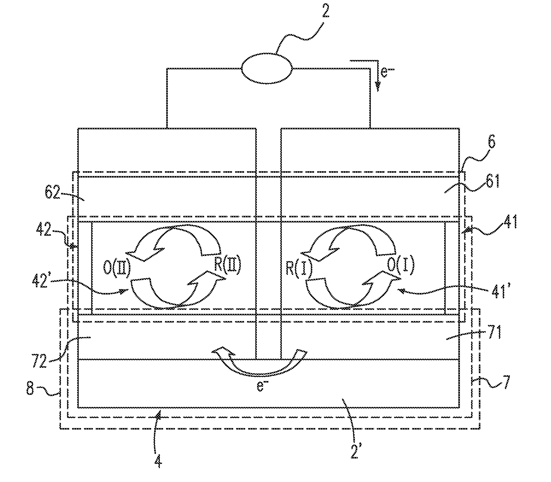
[0058]14. A photocatalyst galvanic cell system, comprising:[0059]a first trough including a first mediator, a first photo-electrode and a first galvanic electrode, wherein the first mediator absorbs a solar energy to generate a first mediator product to be provided to the first galvanic electrode; and[0060]a second trough including a second mediator, a second photo-electrode and a second galvanic electrode, wherein the second mediator absorbs the solar energy to generate a second mediator product to ...
embodiment 14
[0061]15. The photocatalyst galvanic cell system of Embodiment 14, further comprising a cocatalyst.
[0062]16. The photocatalyst galvanic cell system of any one of Embodiments 14-15, wherein:[0063]the cocatalyst serves as one of a sacrificial reagent and a catalyst carrier.
[0064]17. The photocatalyst galvanic cell system of any one of Embodiments 14-16, wherein the cocatalyst is included in the first photo-electrode and the second photo-electrode.
[0065]18. The photocatalyst galvanic cell system of any one of Embodiments 14-17, wherein the cocatalyst is included in the first galvanic electrode and the second galvanic electrode.
[0066]19. The photocatalyst galvanic cell system of any one of Embodiments 14-18, wherein when the first photo-electrode is an anode and the second photo-electrode is a cathode, the first mediator product is an oxidizer and the second mediator product is a reductant.
[0067]20. The photocatalyst galvanic cell system of any one of Embodiments 14-19, wherein the oxid...
PUM
 Abstract
Description
Claims
Application Information