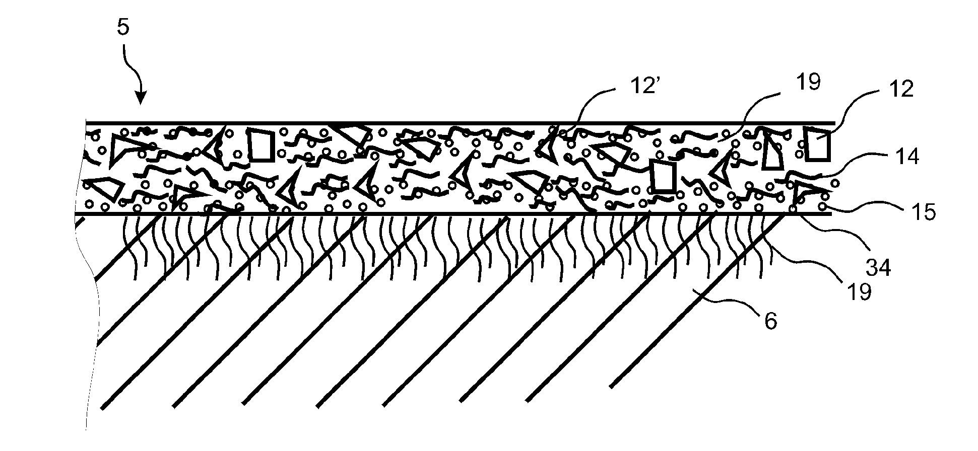
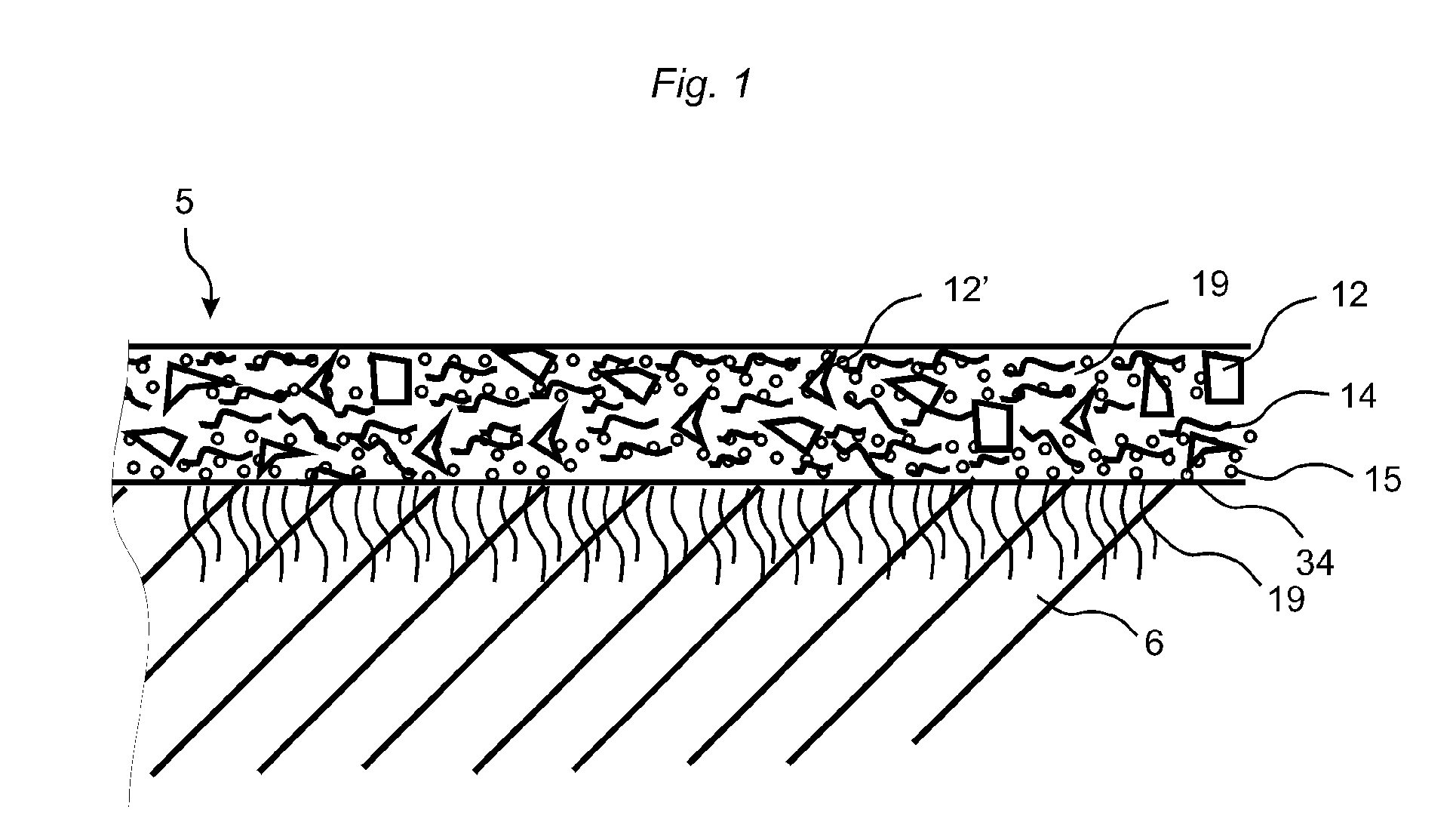
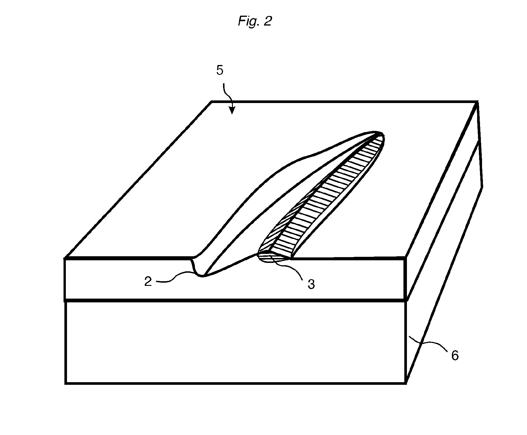
Heat and pressure generated design
a technology of heat generation and pressure generation, applied in the field of fibre-based panels, can solve the problems of crazing surface of deep structures, and achieve the effects of optimizing the water resistance of the locking system area, reducing the cost of formulation, and increasing chemical and mechanical properties
- Summary
- Abstract
- Description
- Claims
- Application Information
AI Technical Summary
Benefits of technology
Problems solved by technology
Method used
Image

Examples
example 1
High Structure, Normal Pressure
[0042]Scattered amount: 600 g / m2
[0043]Carrier board: 8 mm HDF
[0044]Backing: 2 layers of NKR 140
[0045]Structure plate: 0.7 mm Slate Structure
[0046]Pressure: 45 kg / cm2,
[0047]Contact time: 25 sec
[0048]Press plate temperature: 160° C.
One Surface Layer—Scattered Homogenously
[0049]
ComponentWt-%Melamine Formaldehyde resin33Wood Fibre43Wear Resistant Particles: Aluminum Oxide13Coloring Substance: Titanium Dioxide11Sum100
[0050]The mass ratio between Melamine Formaldehyde Resin and dry components (Wood Fibre,
[0051]Coloring Substance) is equal to 61%. The mass ratio between Melamine Formaldehyde Resin and Wood Fibre is equal to 77%. The resulting product is a homogenous off white product.
example 2
High Structure, Normal Pressure
[0052]Scattered amount: 600 g / m2
[0053]Carrier board: 8 mm HDF
[0054]Backing: 2 layers of NKR 140
[0055]Structure plate: 0.7 mm Slate Structure
[0056]Pressure: 45 kg / cm2,
[0057]Contact time: 25 sec
[0058]Press plate temperature: 160° C.
One Surface Layer—Scattered Homogenously
[0059]
ComponentWt-%Melamine Formaldehyde resin47Wood Fibre25Wear Resistant Particles: Aluminum Oxide17Coloring Substance: Titanium Dioxide11Sum100
[0060]The mass ratio between Melamine Formaldehyde Resin and dry components (Wood Fibre, Coloring Substance) is equal to 131%. The mass ratio between Melamine Formaldehyde Resin and Wood Fibre is equal to 188%. The resulting product is a substantially homogenous off white product with some whiter spots at the ridges of the embossed structure.
example 3
High Structure, Normal Pressure
[0061]Scattered amount: 600 g / m2
[0062]Carrier board: 8 mm HDF
[0063]Backing: 2 layers of NKR 140
[0064]Structure plate: 0.7 mm Slate Structure
[0065]Pressure: 45 kg / cm2,
[0066]Contact time: 25 sec Press plate temperature: 160° C.
One Surface Layer—Scattered Homogenously
[0067]
ComponentWt-%Melamine Formaldehyde resin65Wood Fibre17Wear Resistant Particles: Aluminum Oxide11Coloring Substance: Titanium Dioxide7Sum100
[0068]The mass ratio between Melamine Formaldehyde Resin and dry components (Wood Fibre, Coloring Substance) is equal to 271%. The mass ratio between Melamine Formaldehyde Resin and Wood Fibre is equal to 382%. The resulting product is a substantially homogenous off white product with many whiter spots at the ridges of the embossed structure.
PUM
| Property | Measurement | Unit |
|---|---|---|
| depth | aaaaa | aaaaa |
| concentration | aaaaa | aaaaa |
| wear resistant | aaaaa | aaaaa |
Abstract
Description
Claims
Application Information
 - R&D
- Intellectual Property
- Life Sciences
- Materials
- Tech Scout
- Unparalleled Data Quality
- Higher Quality Content
- 60% Fewer Hallucinations
Browse by: Latest US Patents, China's latest patents, Technical Efficacy Thesaurus, Application Domain, Technology Topic, Popular Technical Reports.
© 2025 PatSnap. All rights reserved.Legal|Privacy policy|Modern Slavery Act Transparency Statement|Sitemap|About US| Contact US: help@patsnap.com