
Intra-cardiac implantable medical device with IC device extension for lv pacing/sensing

a technology of implantable medical devices and ic devices, which is applied in the direction of internal electrodes, transvascular endocardial electrodes, therapy, etc., can solve the problems of requiring multiple leads, unable to meet the pacing/sensing capability of left ventricle pacemakers, and experiencing certain limitations

Inactive Publication Date: 2014-06-19
PACESETTER INC
View PDF14 Cites 57 Cited by
  • Summary
  • Abstract
  • Description
  • Claims
  • Application Information

AI Technical Summary

Benefits of technology

The patent describes an assembly for introducing a device into the heart of a patient for treating various heart conditions. The assembly includes a sheath with a flexible tube and a pusher rod for maneuvering the device. The device has an anchor at one end for attachment to the heart and can be positioned at different locations within the heart. The assembly also includes an IC device extension that can be positioned in a coronary vein or a lateral coronary sinus to stimulate the heart at a desired location. The technical effects of this invention include improved precision and accuracy in positioning the device within the heart and improved heart function.

Problems solved by technology

These leads may experience certain limitations, such as incidences of venous stenosis or thrombosis, device-related endocarditis, lead perforation of the tricuspid valve and concomitant tricuspid stenosis; and lacerations of the right atrium, superior vena cava, and innominate vein or pulmonary embolization of electrode fragments during lead extraction.
Further, conventional pacemakers with left ventricle (LV) pacing / sensing capability require multiple leads and a complex header on the pacemaker.
LLPM devices, that have been proposed thus far, offer limited functional capability.
For example, an LLPM device that is located in the right atrium would be limited to offering AAI mode functionality.
Similarly, an LLPM device that is located in the right ventricle would be limited to offering VVI mode functionality.
However, these sets of multiple LLPM devices experience various limitations.
This pacing and sensing information is necessary to maintain continuous synchronous operation, which in turn draws a large amount of battery power.
Further, it is difficult to maintain a reliable wireless communications link between LLPM devices.
Hence, the potential exists that the communications link is broken or intermittent.

Method used


Image

  • Intra-cardiac implantable medical device with IC device extension for lv pacing/sensing
  • Intra-cardiac implantable medical device with IC device extension for lv pacing/sensing
  • Intra-cardiac implantable medical device with IC device extension for lv pacing/sensing

Examples


Embodiment Construction

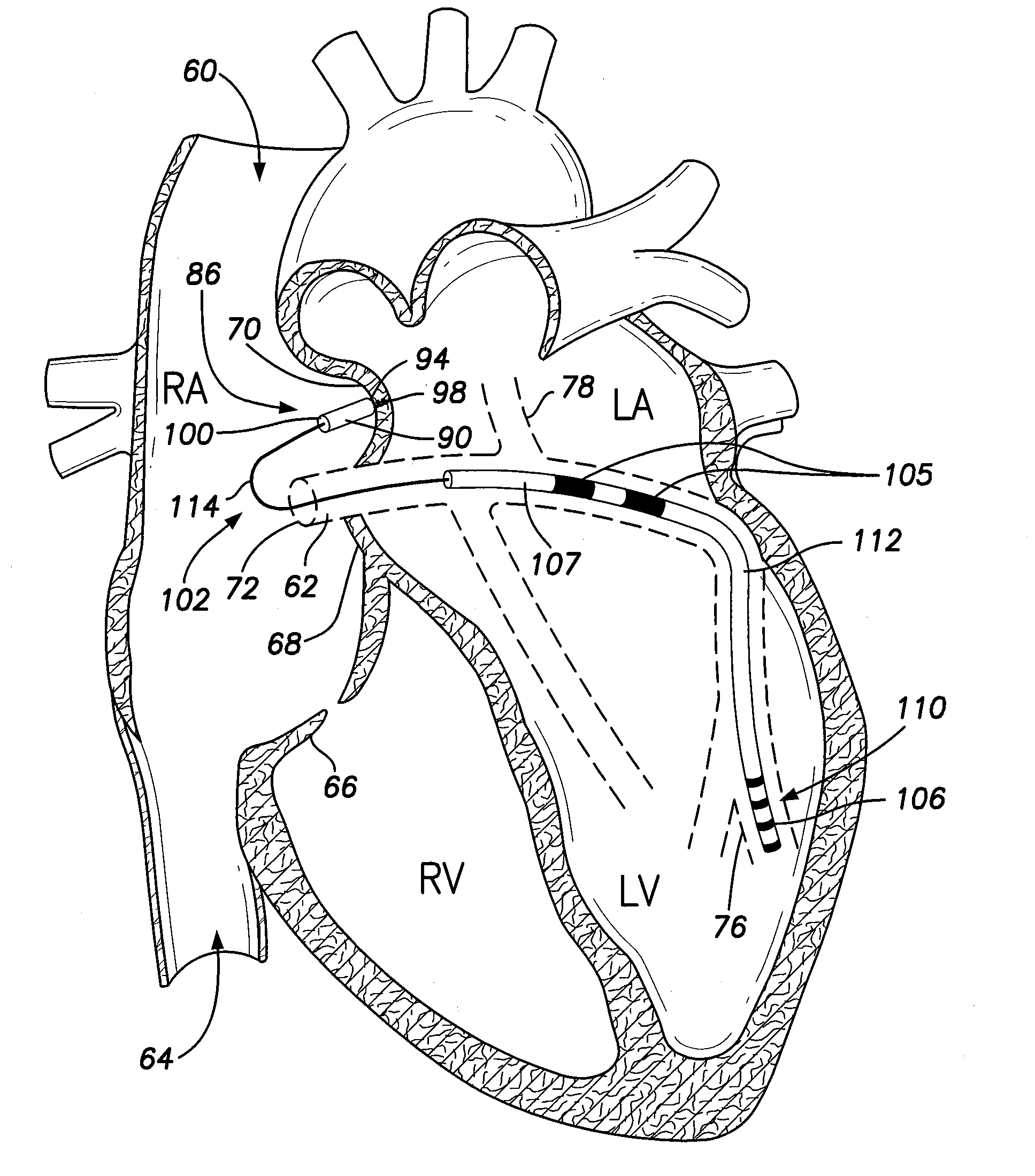
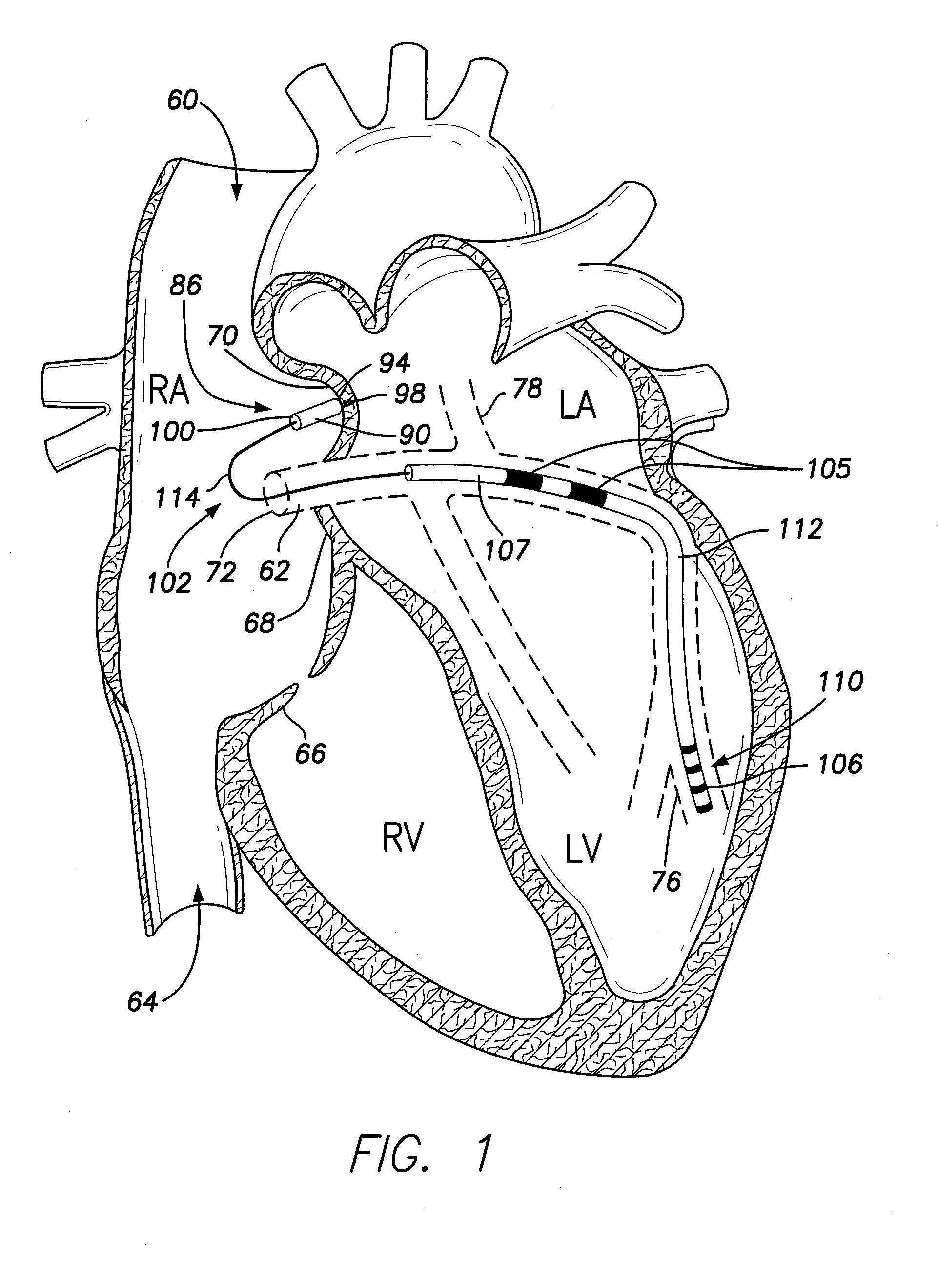
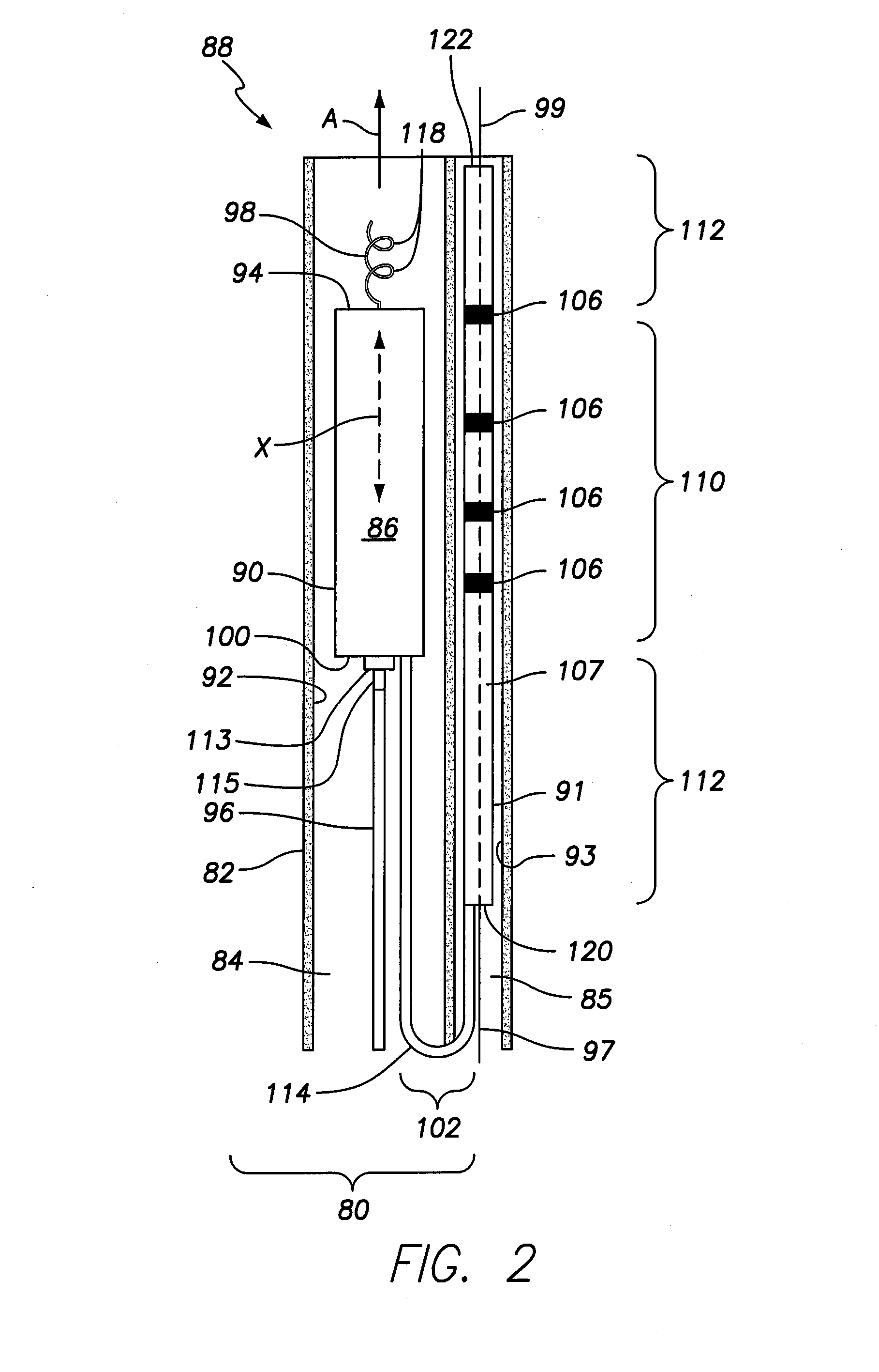
[0036]FIG. 1 provides a sectional view of the patient's heart, showing the right and left atrium (RA and LA), and right and left ventricles (RV and LV), with an intra-cardiac implantable medical device (IIMD) 86 and intra-cardiac (IC) device extension 102 (also referred to as an ICDE) implanted in accordance with an embodiment of the present invention. The IIMD 86 may have been placed through the superior vena cava (SVC) or inferior vena cava (IVC) into the right atrium of the heart. As shown in FIG. 1, the right atrium wall includes the superior vena cava inlet 60, coronary sinus 62, IVC inlet 64, tricuspid valve 66, and the ventricular vestibule (VV) region 68. The ostium (OS) 72 illustrates the juncture of the coronary sinus 62 and the RA. The coronary sinus branches into various tributary vessels such as the lateral veins, great cardiac vein, middle cardiac vein, small cardiac vein, anterior inter-ventricular veins and the like. In FIG. 1, the lateral cardiac vein 76 and vein of...


PUM


Abstract

An assembly is provided for introducing a device within a heart of a patient. The assembly is comprised of a sheath having at least one internal passage. An intra-cardiac implantable medical device (IIMD) is retained within the at least one internal passage, wherein the IIMD is configured to be discharged from a distal end of the sheath. The IIMD has a housing with a first active fixation member configured to anchor the IIMD at a first implant location within a local chamber of the heart.

Description

FIELD OF THE INVENTION[0001]Embodiments of the present invention generally relate to intra-cardiac implantable devices and methods for implanting the same. Embodiments more particularly relate to intra-cardiac implantable medical devices that utilize an IC device extension to afford dual chamber functionality.BACKGROUND OF THE INVENTION[0002]Currently, permanently-implanted pacemakers (PPMs) utilize one or more electrically-conductive leads (which traverse blood vessels and heart chambers) in order to connect a canister with electronics and a power source (the can) to electrodes affixed to the heart for the purpose of electrically exciting cardiac tissue (pacing) and measuring myocardial electrical activity (sensing). These leads may experience certain limitations, such as incidences of venous stenosis or thrombosis, device-related endocarditis, lead perforation of the tricuspid valve and concomitant tricuspid stenosis; and lacerations of the right atrium, superior vena cava, and in...

Claims


Application Information

Patent Timeline
IPC IPC(8): A61N1/362A61N1/365
CPCA61N1/365A61N1/362A61N1/057A61N1/368A61N1/37205A61N1/3756A61N2001/0585A61N1/37512A61N1/37518
Inventor BORNZIN, GENE A.POORE, JOHN W.SOMOGYI, ZOLTANMIN, XIAOYITHERET, DIDIER
Owner PACESETTER INC
Learn More