
Pick For Earthworking Machine

a technology for earthworking machines and cutters, applied in the field of cutters, can solve the problems of inefficient operation of picks, high heat generation of the tips, and inefficient heat generation of the tips, and achieve the effects of reducing costs, reducing complexity, and efficient transfer

Inactive Publication Date: 2014-06-26
ESCO HYDRA UK
View PDF5 Cites 27 Cited by
  • Summary
  • Abstract
  • Description
  • Claims
  • Application Information

AI Technical Summary

Benefits of technology

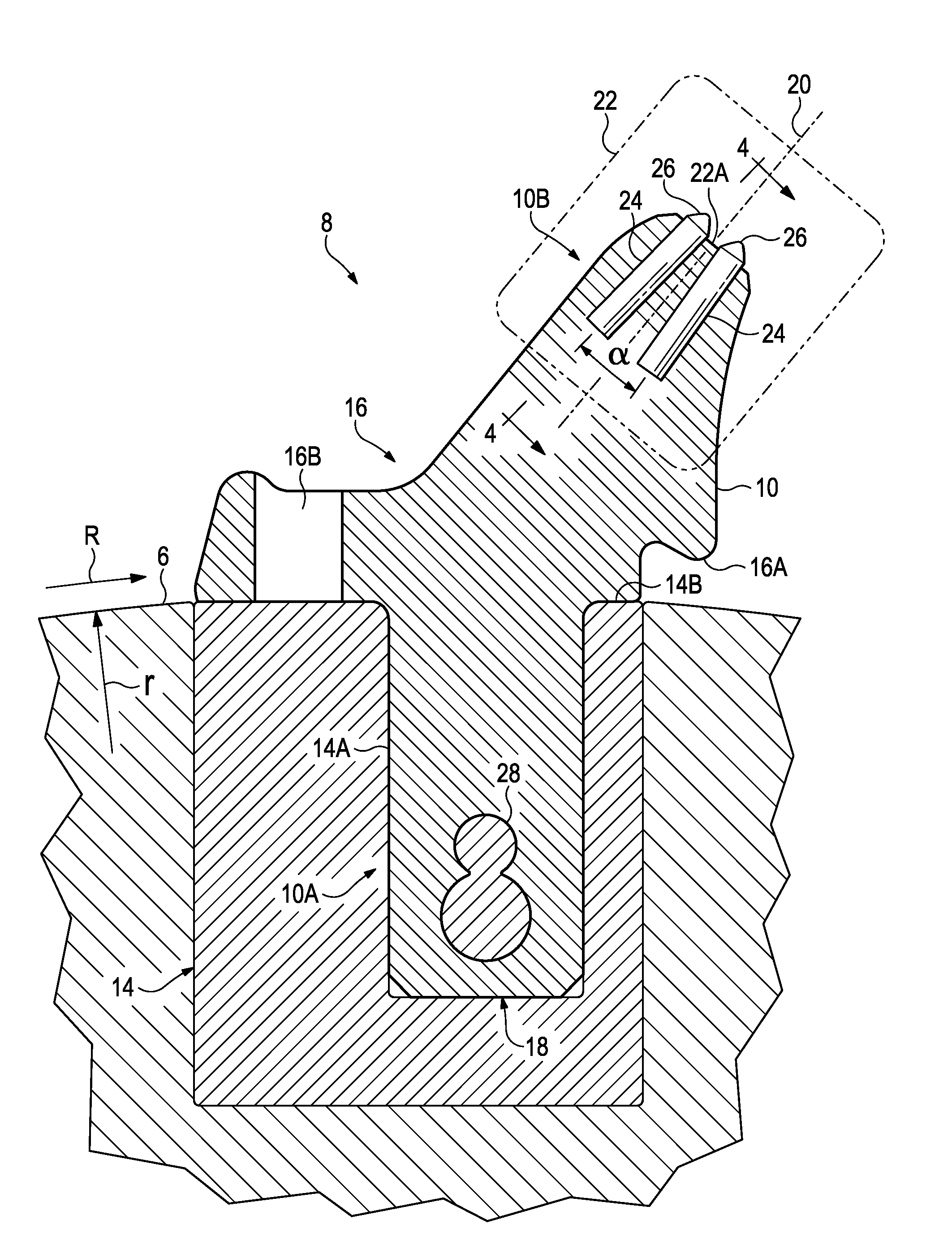
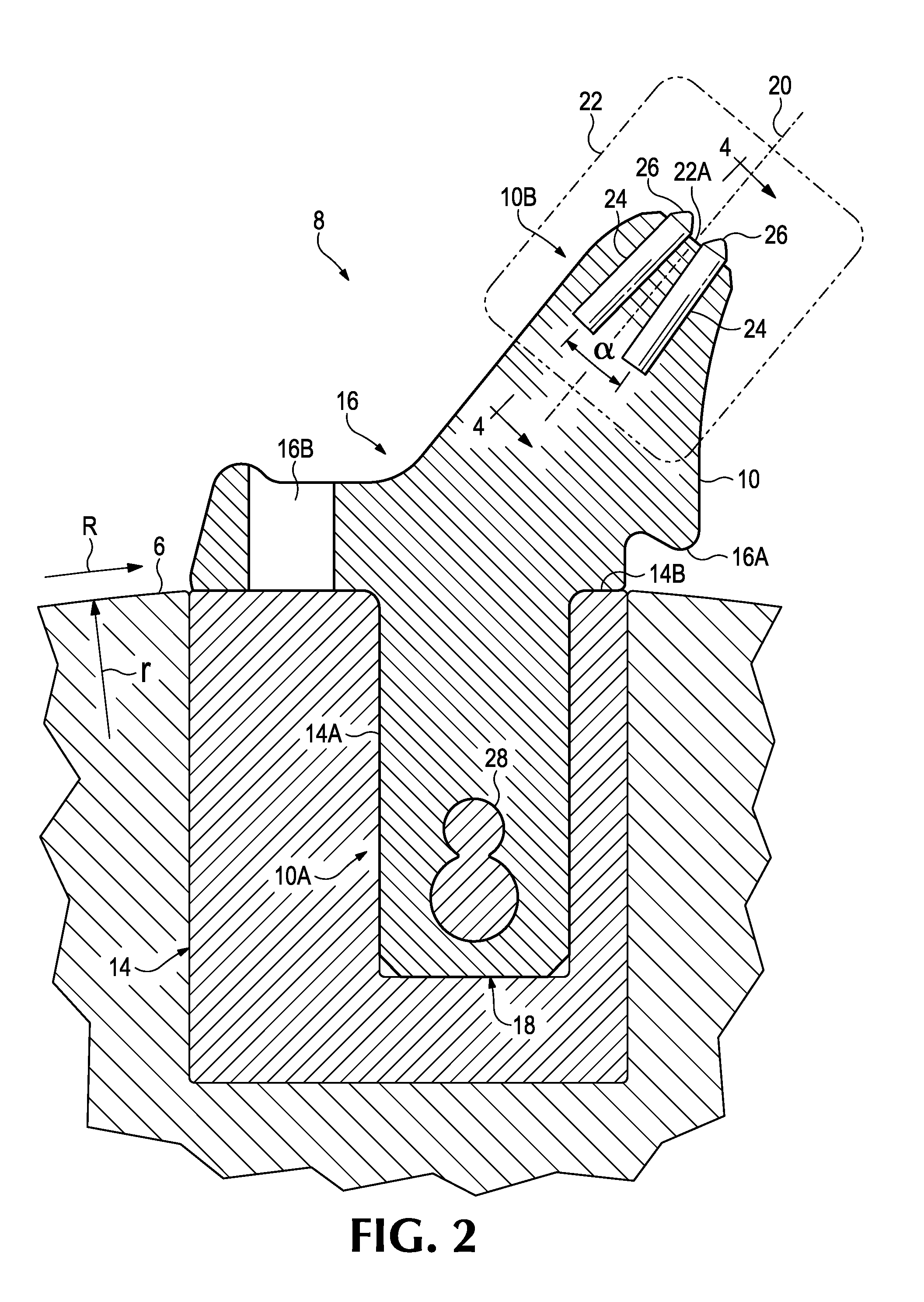
The present invention is about an improved pick used on mining and construction machines. The pick has a head with multiple tips that impact the surface being worked. The tips are positioned in holes in the pick head and are made of a hard material such as rods that are smaller than the holes. This design helps to efficiently transfer heat from the tips to the rest of the pick. The pick can be used with multiple inserts in the head, which further helps to dissipate the heat. The pick can be designed to have the inserts positioned in different ways, such as parallel or converging, depending on the machine and material being worked. By using this improved pick design, machine downtime and power consumption can be reduced, and the life of the pick can be extended.

Problems solved by technology

In operation, the impact of the tips can generate significant heat.
Dissipation of this heat is critical as the carbide tips are subject to thermal fatigue when they consistently reach or operate at high temperatures.
Inefficient operation of the picks due to damage or wear can also generate excessive heat, raising the temperature of proximate parts of the drum and significantly degrading structural properties of components.
The head of a pick may be damaged by inadvertent collision with a roof support or by hitting hard inclusions in the ore seam such as rocks.
The damaged pick then sustains more damage which results in a shortened useful life and lower machine efficiency.

Method used


Image

  • Pick For Earthworking Machine
  • Pick For Earthworking Machine
  • Pick For Earthworking Machine

Examples


Embodiment Construction

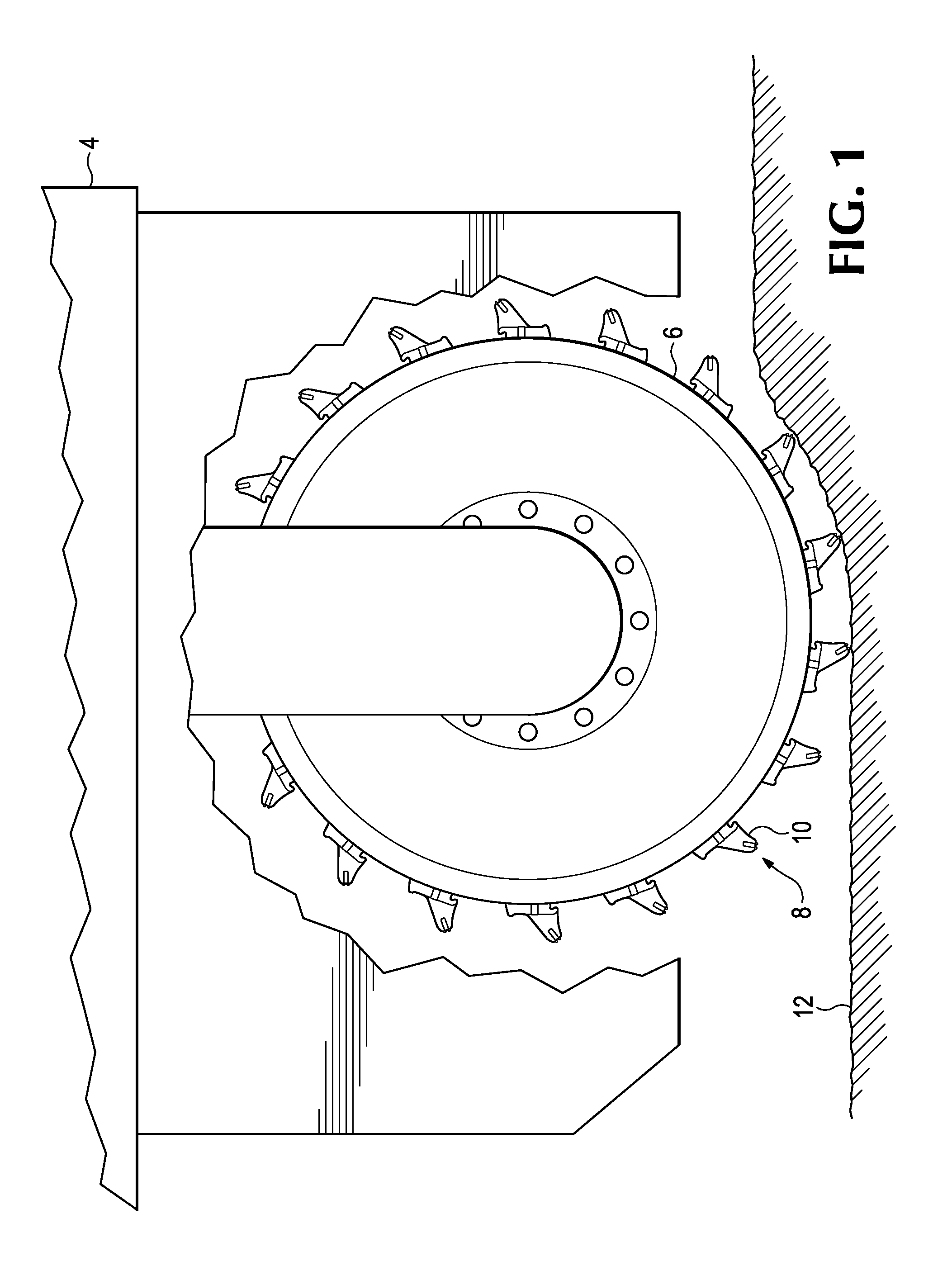
[0021]FIG. 1 depicts an earth working operation including a face miner with pick assemblies for extracting earthen material such as coal in a mining operation. The operation is shown as including a mining machine 4 with a driven drum, roll or cylindrical body 6 mounted with pick assemblies 8 including picks 10 for impacting the ore seam or consolidated earthen material 12 as drum 6 rotates. Picks 10 are mechanically attached or secured to rotating drum or cylindrical body 6. Earthen material 12 to be extracted is typically in a seam and rotating drum 6 passes across the mine face so the picks impact the face and dislodge material from the seam in manageable portions. Picks 10 impinge on the material with adequate speed and force to fracture the material.

[0022]The spacing of the picks determines the size of the dislodged material, but also is a factor in stress on individual picks and heating of components. The mined material is typically dropped onto a conveyor and transported away ...


PUM


Abstract

A pick to be used on an earth working roll for mining, construction and public works machines such as crushers, surface miners, milling machines and the like. The pick includes a working end with holes that extend into the pick and inserts are received into the holes. The inserts during operation impact and fracture a consolidated material to separate the material. Impacting the material generates heat in the pick at the working end of the pick which must be dissipated and attenuated to limit thermal fatigue in the inserts that occurs at high temperatures. The inserts in the working end are configured to dissipate the generated thermal energy from the inserts to the body of the pick.

Description

FIELD OF THE INVENTION[0001]This invention relates to a cutter tool, primarily for use in mineral winning, such as coal mining, but also usable for other underground purposes such as tunnel or roadway driving, or above ground for civil engineering works such as road planing and trench cutting, whether with drums or endless chains, both on land and underwater.BACKGROUND OF THE INVENTION[0002]A number of machines involved in mining, construction and public works use rolls or drums that are driven for the crushing, mining, milling and the like of earthen materials. These earth working rolls or drums include an array of pick assemblies to engage and separate a consolidated material into smaller portions that can be further separated in subsequent operations. A pick assembly may include a pick releasably attached to a holder secured to the drum or roll. The pick includes a head configured to contact the material and separate it. The picks are wear parts that are replaced after a certain ...

Claims


Application Information

Patent Timeline
IPC IPC(8): E21C35/183
CPCE21C35/183
Inventor WARREN, JOHN JOSEPH
Owner ESCO HYDRA UK
Learn More