Implant delivery system and implants

Inactive Publication Date: 2014-06-26
VOLCANO CORP
View PDF12 Cites 61 Cited by
  • Summary
  • Abstract
  • Description
  • Claims
  • Application Information

AI Technical Summary

Benefits of technology

[0014]In order to facilitate deployment of the implant out of the center lumen and into a body lumen, the inner member can include a push element configured to engage with the implant. For example, the push element may include a substantially flat surface that is flush with the wall of the center lumen. The push element may form the distal end of the inner member. In certain embodiments, the inner member further

Problems solved by technology

In some circumstances, the thrombus may break off and travel through the blood stream causing serious health issues.
For example, when a thrombus of the lower extremities breaks off, the thrombus may travel through the lungs and cause a pulmonary embolism.
A pulmonary embolism is a blockage of the blood supply to the lungs that causes severe hypoxia and cardiac failure.
It frequently results in death.
However, such therapy is often ineffective for preventing recurrent thrombi or is not suitable for use in patient with acute sensitivity to heparin.
However, th

Method used


Image

  • Implant delivery system and implants
  • Implant delivery system and implants
  • Implant delivery system and implants

Examples


Embodiment Construction

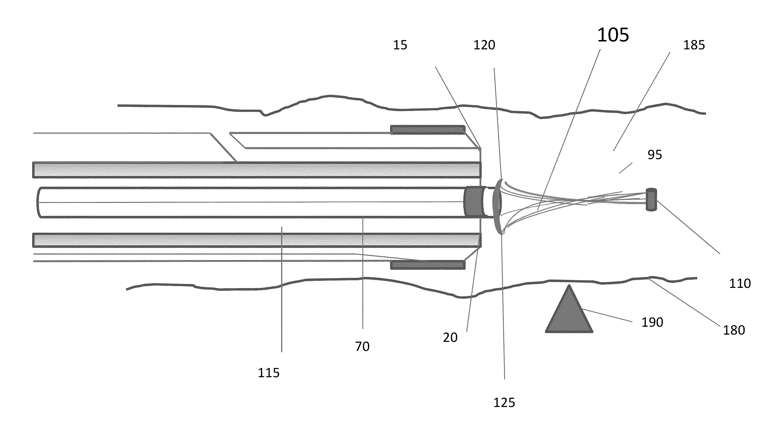
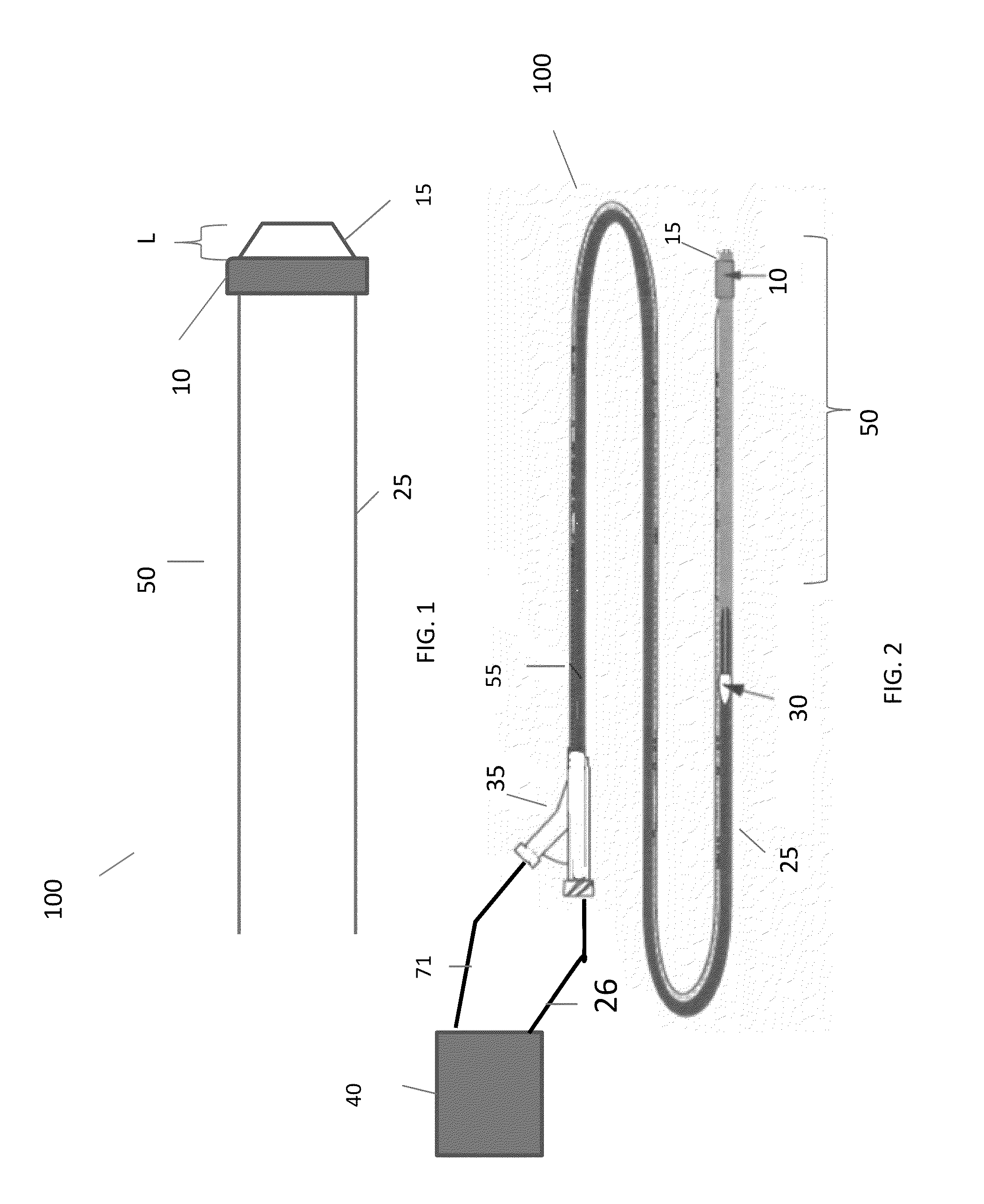
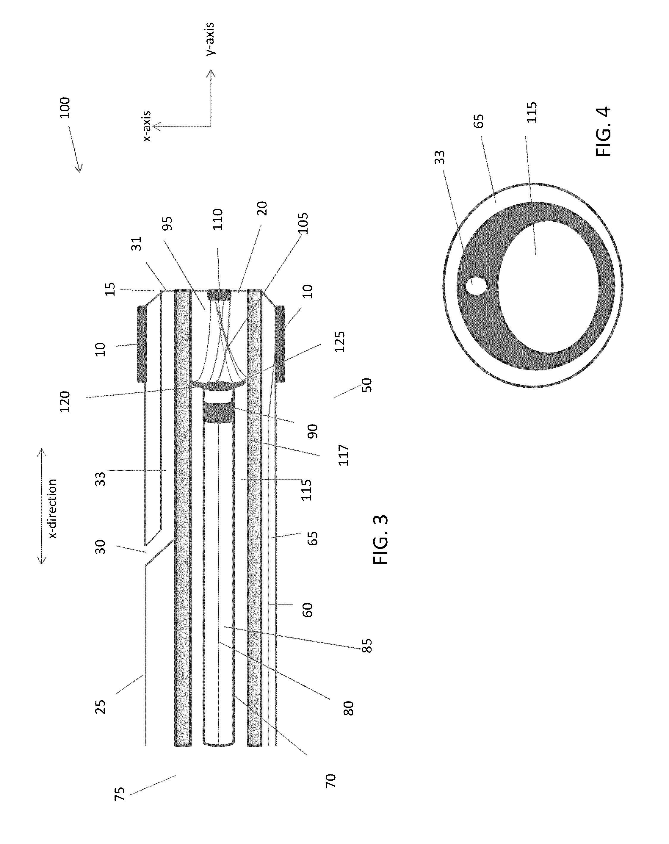
[0027]The present invention generally relates to delivery systems with combined intraluminal implant delivery and imaging capabilities. The delivery systems of the invention provide for 1) real-time imaging of intraluminal surfaces to detect a location of interest (e.g. implantation site); 2) delivery of an implant into the implantation site; and 2) real-time imaging of the implant as engaged with the intraluminal surface without interfering with the implant as implanted. Because the above features are accomplished with one system introduced into a body lumen, this present invention eliminates the need to introduce multiple catheters into the body. For example, there is no need to introduce and remove an imaging catheter to locate a region of interest, then introduce and remove a delivery catheter to deliver an implant, and then re-introduce the imaging catheter to evaluate the implant as implanted.

[0028]The delivery system may be used to deliver any suitable implant into a body lum...


PUM


Abstract

The invention generally relates to devices and methods that allow an operator to obtain real-time images of a luminal surface during an implant delivery procedure. In certain embodiments, a delivery device of the invention includes an elongate body and an inner member moveably disposed within the elongate body. The elongate body includes a first imaging element and defining a center lumen that leads to an opening. The elongate body is configured to releasably hold an implant within the center lumen and the first imaging element is configured to at least partially surround the center lumen such that the implant is deployable through the first imaging element. The inner member is configured to engage with and deploy the implant out of the opening of the elongate body and into a body lumen.

Description

RELATED APPLICATIONS[0001]This application claims the benefit of and priority to U.S. Provisional Ser. No. 61 / 740,196, filed on Dec. 20, 2012, and U.S. Provisional Ser. No. 61 / 777,619, filed Mar. 12, 2013. The entirety of each application is incorporated by reference herein.TECHNICAL FIELD[0002]The present invention generally relates to an apparatus and method for guided intraluminal placement of implants, such as vena cava filters, into the vasculature.BACKGROUND OF THE INVENTION[0003]Deep vein thrombosis is a medical condition that results from the formation of a blood clot, or thrombus, within a vein. Thrombi often develop in the calves, legs, or other lower abdomen, but may occur in other vessels. The clot is typically formed from a pooling of blood within the vein due to abnormally long periods of rest, e.g. when an individual is bed ridden following surgery or suffering a debilitating illness. Other causes of thrombosis include genetic deficiencies, autoimmune disorders, and e...

Claims


Application Information

Patent Timeline
IPC IPC(8): A61B5/06A61B8/08
CPCA61B8/12A61B8/445A61B2560/066A61B5/0066A61B5/0084A61B5/076A61F2/966A61F2250/0096A61B5/065A61B6/022A61B6/12A61B6/487A61B6/504A61F2/011A61B5/06
Inventor STIGALL, JEREMYLAUINGER, JOSEPHGOODMAN, DAVID
Owner VOLCANO CORP
Why Eureka
Try Eureka