Axial Piston Internal Combustion Engine Using an Atkinson Cycle

a technology of internal combustion engine and atkinson cycle, which is applied in the direction of reciprocating piston engine, combustion engine, positive displacement engine, etc., can solve the problems of not being able to benefit from the thermodynamic advantages of overexpansion, the rocker mechanism used to actuate the piston movement is rather complex, and add a significant amount of cost to the production of the engine, so as to reduce the overall engine friction, increase the friction in the engine, and reduce the overall engine efficiency

Inactive Publication Date: 2014-07-03
ROBARDS BRIAN
View PDF7 Cites 1 Cited by
  • Summary
  • Abstract
  • Description
  • Claims
  • Application Information

AI Technical Summary

Problems solved by technology

The issues with most four stroke internal combustion engines is that during the power stroke the piston expansion ratio is limited by the engine architecture, this results in the pressure resulted from the energy of the burned fuel not being able to produce the optimum amount of power.
This engine design was such that the lengths of the intake / compression and expansion / exhaust strokes were the same so it did not benefit from the thermodynamic advantages of overexpansion.
The rocker mechanism that is used to actuate the piston movement is rather complex and would add a significant amount of cost to the production of the engine.
The typical valvetrain components are also known to have natural frequency issues that limit the speed at which they can operate, the use of the rotary valves will eliminate these natural frequency issues and allow the engine to operate at higher engine speeds.
A typical engine uses poppet valves which are activated by a camshaft and various lifters / pushrods / cam followers / etc, these parts act to increase the friction in the engine and reduce the overall engine efficiency.

Method used


Image

  • Axial Piston Internal Combustion Engine Using an Atkinson Cycle
  • Axial Piston Internal Combustion Engine Using an Atkinson Cycle
  • Axial Piston Internal Combustion Engine Using an Atkinson Cycle

Examples


Embodiment Construction

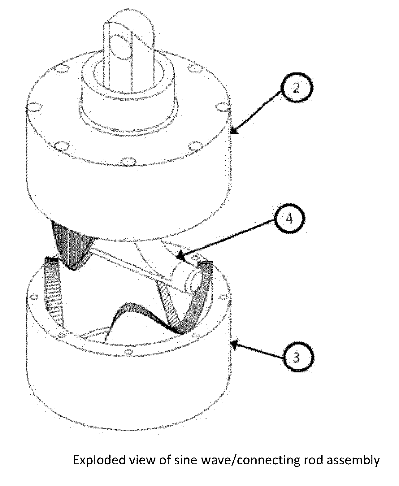
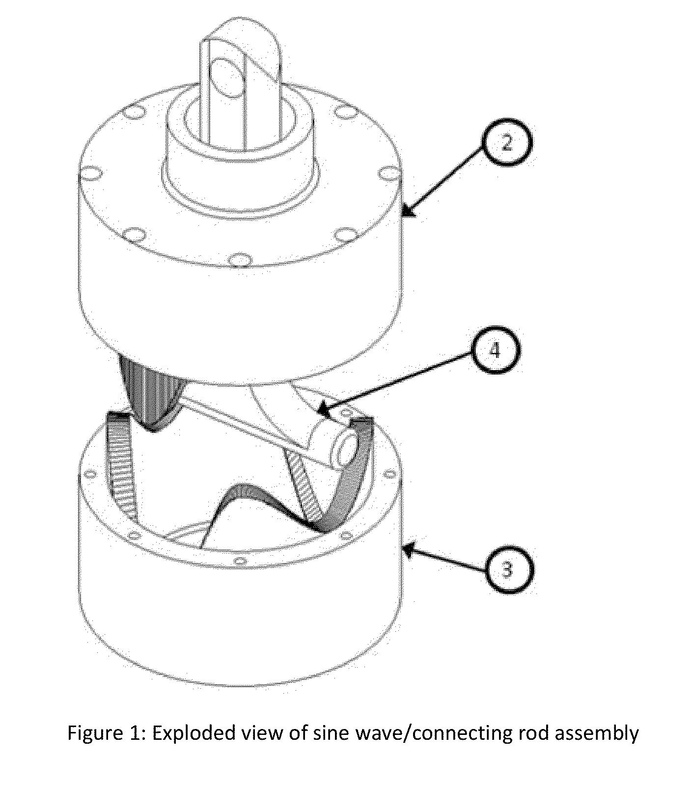
[0052]FIG. 1 is an exploded view of the sine wave / connecting rod assembly (4) which shows the sinusoidal shaped channel in the upper sine wave barrel (2) and lower sine wave barrel (3) and the T-shaped connecting rod (4) which has the two opposing circular ends that ride inside of these channels.

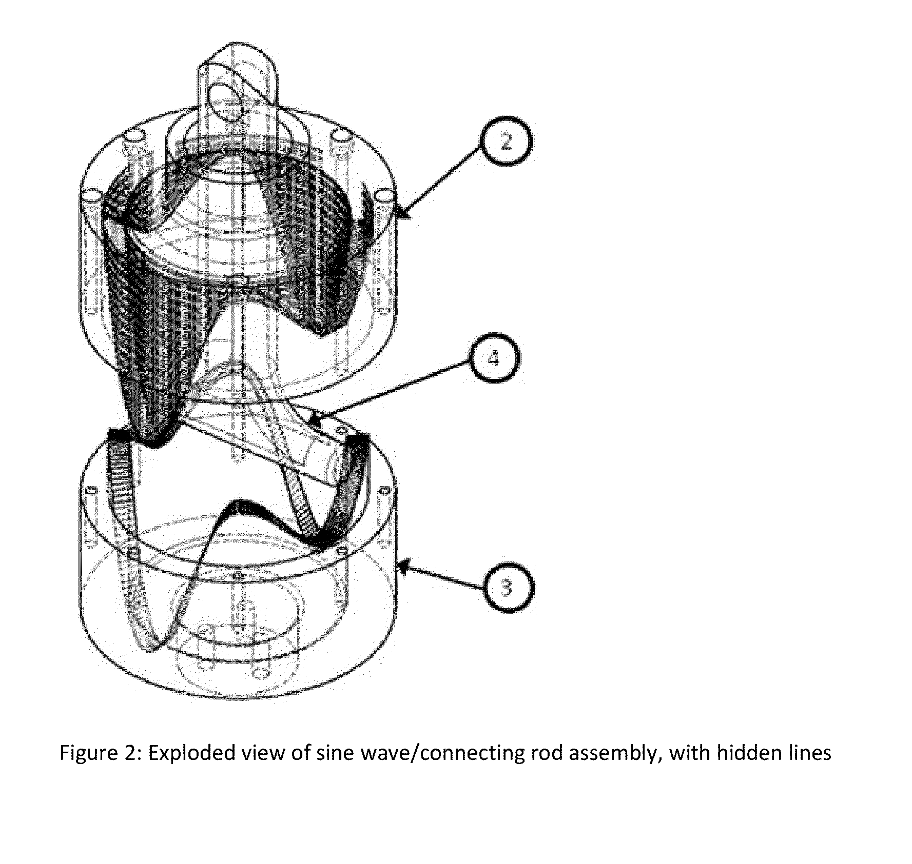
[0053]FIG. 2 is an exploded view similar to FIG. 1 which shows the complete shape of the sinusoidal channels in the upper since wave barrel (2) and the lower sine wave barrel (3).

[0054]FIG. 3 is an upper rear isometric view showing the engine block (1) with the five radially positioned cylinders. Each cylinder has the sine wave / connecting rod assembly (4) installed using a lower main bearing (8), upper main bearing (7) and two thrust bearings (9) mounted both above and below the sine wave / connecting rod assembly (4) for each cylinder. This figure also shows that a piston (6) is installed in each cylinder and a connecting rod bushing (10) is installed around the connecting rod of each cylinde...


PUM


Abstract

An axial piston internal combustion engine designed to improve the thermal efficiency of the engine by utilizing a sine wave / connecting rod assembly (5) to cause the piston (6) of the engine to travel vertically parallel to the engine's main shaft (13). The upper sine wave barrel (2) and lower sine wave barrel (3) have a channel in them that the cylindrical ends of the connecting rod (4) travel in, forcing the connecting rod (4) and piston (6) to travel vertically. The engine also utilizes slide valve (20) that has slots in it that when slid past the ports of the upper cylinder head (18) and lower cylinder head (19) controls the intake and exhaust timing events of the engine. The channel in the upper sine wave barrel (2) and lower sine wave barrel (3) is designed such that the vertical expansion / exhaust strokes of the engine are longer than the intake / compression strokes which allow the engine to make more efficient use of the energy produced by combusting the fuel, improving the thermal efficiency of the engine. The design also reduces the friction between the cylinder walls and piston (4) and the friction associated with typical engines valvetrain components, improving the overall efficiency of the engine. By reducing the frictional losses and improving the thermal efficiency the new engine should have decreased fuel consumption.

Description

CROSS-REFERENCE TO RELATED APPLICATIONS[0001]This application claims the benefits of provisional patent application Ser. No 61582398 filed 2012 Jan. 1 by the present inventor.SEQUENCE LISTING[0002]NoneBACKGROUNDPrior Art[0003]The following is a tabulation of some prior art that presently appears relevant:US PatentsPat. No.Issue DatePatentee6,202,6062001-03-20Anttila2010 / 01808682010-07-22Scalzo4,944,2611990-07-31Coates[0004]This relates to internal combustion engines, specifically four stroke internal combustion engines which utilize an axial piston arrangement. Four stroke internal combustion engines tend to not use all of the thermal energy of the fuel that they burn to produce power, if the engines were to be designed in a way which would improve the thermal efficiency the power produced would increase and the fuel consumption would decrease. The issues with most four stroke internal combustion engines is that during the power stroke the piston expansion ratio is limited by the en...

Claims


Application Information

Patent Timeline
Patent Type & Authority Applications(United States)
IPC IPC(8): F02B75/28
CPCF02B75/28F01B1/10F01B1/12F01B3/04F02B75/26Y02T10/12F01B3/045F01B9/06
Inventor ROBARDS, BRIAN
Owner ROBARDS BRIAN
Why Eureka
Try Eureka