Battery control apparatus
- Summary
- Abstract
- Description
- Claims
- Application Information
AI Technical Summary
Benefits of technology
Problems solved by technology
Method used
Image
Examples
embodiment 1
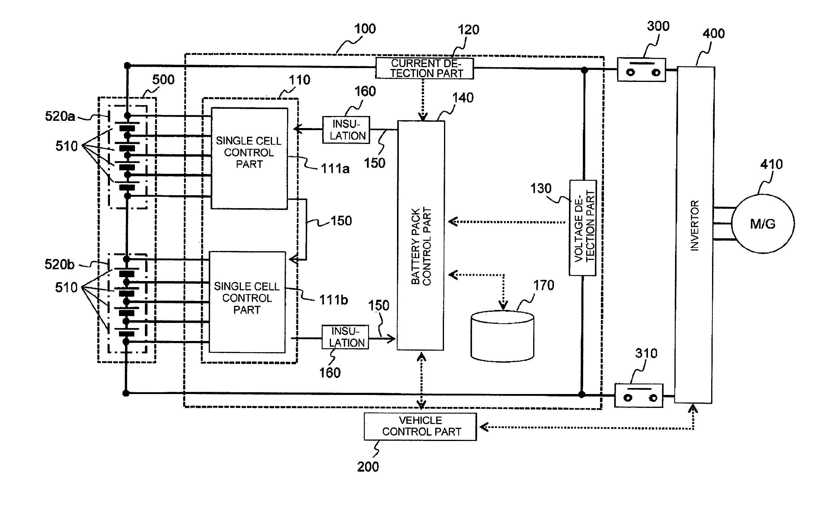
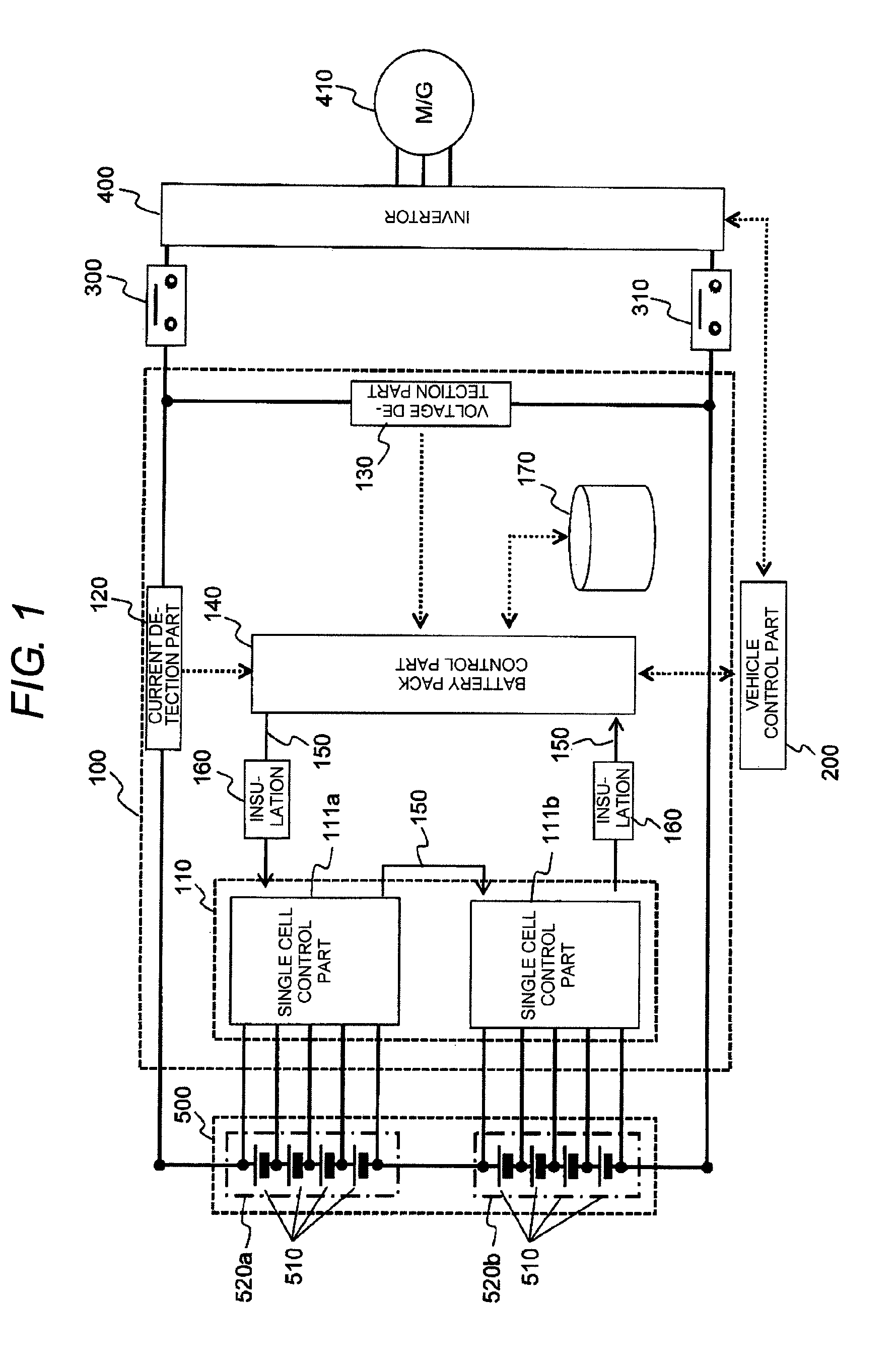
[0063]As described above, the battery control apparatus 100 of the embodiment 1 restricts the permitted charge power of the battery pack 500 according to the degree of closeness of the CCV of the single cell 510 to the upper limit of the permitted power restricted range. By this, the charge power is restricted before the inter-terminal voltage of the single cell 510 exceeds the permitted range and the single cell 510 can be protected.
[0064]Besides, the battery control apparatus 100 of the embodiment 1 performs the control process to keep the inter-terminal voltage of the single cell 510 within the permitted range in units of the battery pack 500. By this, since the control process can be simplified, this is advantageous from the viewpoint of calculation load and the like.
Embodiment 2
[0065]In the embodiment 1, the example is described in which the single cell 510 is protected by restricting the permitted charge power. The same method can be used also in an operation at the time of di...
embodiment 2
[0085]As described above, the battery control apparatus 100 of the embodiment 2 restricts the permitted discharge power of the battery pack 500 in accordance with the degree of closeness of the CCV of the single cell 510 to the lower limit value of the permitted power restricted range. By this, the discharge power is restricted before the inter-terminal voltage of the single cell 510 exceeds the permitted power restricted range, and an appropriate discharge amount can be obtained.
[0086]Incidentally, it is needless to say that the charge control method described in the embodiment 1 and the discharge control method described in the embodiment 2 are combined, and the optimum control can be performed both at the time of charge and discharge.
embodiment 3
[0087]Although the SOC of the battery pack 500 is obtained by using the SOC table 171 in the embodiments 1 to 2, this can be obtained by another method, for example, by use of a specified arithmetic expression. Similarly, although the permitted charge and discharge powers are obtained by using the permitted charge power table 172 and the permitted discharge power table 174 in the embodiments 1 to 2, these can be obtained by another method, for example, by use of a specified arithmetic expression.
[0088]In the above, although the invention made by the inventor is specifically described based on the embodiments, it is needless to say that the invention is not limited to the embodiments, and various modifications can be made in the range not departing from the gist.
[0089]Besides, the above respective structures, functions and processing parts can be realized as hardware by designing all or part thereof with, for example, an integrated circuit, or can also be realized as software by a pr...
PUM
 Abstract
Description
Claims
Application Information
 - R&D
- Intellectual Property
- Life Sciences
- Materials
- Tech Scout
- Unparalleled Data Quality
- Higher Quality Content
- 60% Fewer Hallucinations
Browse by: Latest US Patents, China's latest patents, Technical Efficacy Thesaurus, Application Domain, Technology Topic, Popular Technical Reports.
© 2025 PatSnap. All rights reserved.Legal|Privacy policy|Modern Slavery Act Transparency Statement|Sitemap|About US| Contact US: help@patsnap.com


