Actuator system and operating method for an actuator system

a technology of actuator system and actuator system, which is applied in the direction of brake system, failure to meet the safety requirements of vehicles, brake components, etc., can solve the problems of increased power demand and loss of actuator efficiency, and achieve the effect of improving integration within the vehicl

Active Publication Date: 2014-07-17
CONTINENTAL TEVES AG & CO OHG
View PDF12 Cites 17 Cited by
  • Summary
  • Abstract
  • Description
  • Claims
  • Application Information

AI Technical Summary

Benefits of technology

[0006]An aspect of the invention provides an improved actuator system and a particularly efficient, improved method of operation for an actuator system, which enables a system improvement based on a holistic approach, and thereby enables improved integration within the vehicle.

Problems solved by technology

There is a criticism that in principle the method described above causes a loss of actuator efficiency, while increased power demands are made on other vehicle systems (on-board electrical system).

Method used


Image

  • Actuator system and operating method for an actuator system
  • Actuator system and operating method for an actuator system
  • Actuator system and operating method for an actuator system

Examples


Embodiment Construction

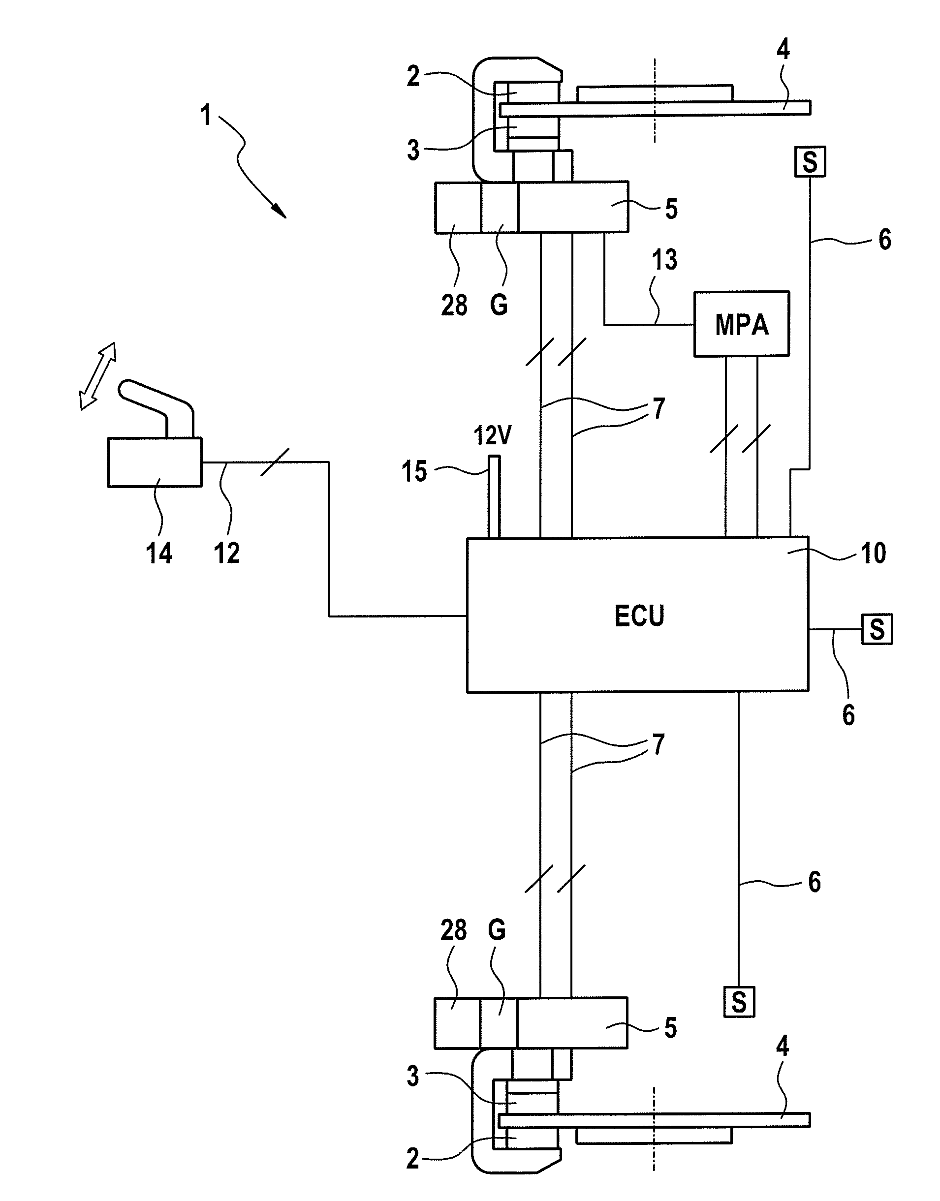
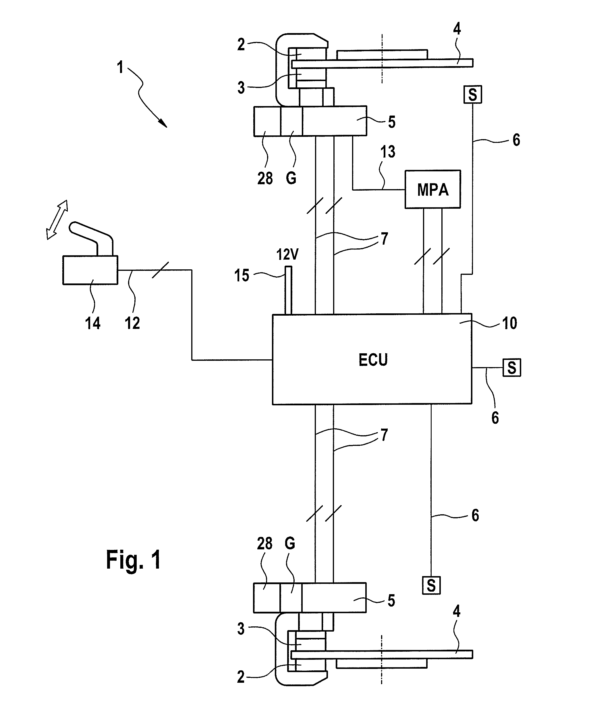
[0013]A known motor vehicle brake system 1 according to FIG. 1 comprises at least one actuator 5 for each wheel of an axle, each of said actuators being connected via one or a plurality of electric supply lines 7 to a control unit 10. FIG. 1 also shows electrical operation of the control unit 10 via a (possibly multiply-redundant) electric line 12 to the operating switch 14 of the parking brake, with which the application or release of the parking brake can be initiated by the driver of the motor vehicle. The control unit 10 comprises an electric voltage supply 15. Furthermore, the actuators 5 can comprise sensors S, such as in particular temperature sensors, revolution rate sensors, force sensors or similar senders, switches or actuation elements, which are connected to the control unit 10 via additional data lines 6 for information transfer. Each actuator comprises an electric motor 28 and a gearbox G and may comprise a brake caliper housing.

[0014]The universal application of an e...


PUM


Abstract

The invention relates to an actuator system, in particular an electromechanical parking brake system, comprising an actuator, wherein the actuator is driven by a direct current motor that can be driven in both directions of rotation, wherein a control unit for controlling the movement of the direct current motor in an open-loop or closed-loop manner is provided. The core of the invention is that one or more pieces of information are supplied to a control unit, said information allowing the application force exerted by the electromotive actuator to be determined and compared to a predetermined minimum application force, and wherein the control unit emits at least one piece of information, signal or the like for requesting an auxiliary actuation to peripheral systems, components and/or electronic control units after the target to actual value comparison has shown that the determined, set application force is smaller than the predetermined minimum application force.

Description

CROSS REFERENCE TO RELATED APPLICATIONS[0001]This application is the U.S. National Phase Application of PCT International Application No. PCT / EP2012 / 061649, filed Jun. 19, 2012, which claims priority to German Patent Application No. 10 2011 077 786.5, filed Jun. 20, 2011, the contents of such applications being incorporated by reference herein.FIELD OF THE INVENTION[0002]The invention relates to an actuator system, especially a service or parking brake, comprising: at least one electronically controlled electromotive actuator; and at least one electronic control unit, which is connected via at least one electric supply line to the actuator, and wherein the control unit is connected to one or to a plurality of switches, senders, sensors S and electric actuating elements and comprises at least one microprocessor with implemented software for performing a regulation strategy for controlled or regulated electrical supply of the actuator, and wherein the actuator system is an electromech...

Claims


Application Information

Patent Timeline
Patent Type & Authority Applications(United States)
IPC IPC(8): B60T13/58B60T17/22B60T13/74
CPCB60T13/58B60T17/22B60T13/74B60T7/085B60T13/588B60T13/741B60T17/221B60T8/17B60T2270/40
Inventor SCHNEIDER, HEINZ-ANTONMARON, CHRISTOF
Owner CONTINENTAL TEVES AG & CO OHG
Why Eureka
Try Eureka