Efficient dilution method, including washing method for immunoassay
- Summary
- Abstract
- Description
- Claims
- Application Information
AI Technical Summary
Benefits of technology
Problems solved by technology
Method used
Image
Examples
first embodiment
[0096]FIG. 3 shows the invention, illustrating an implementation of an exemplary washing method on an EWOD device. FIG. 3a shows a cross-sectional side view of such an EWOD device in which a droplet 2 is sandwiched between glass substrates 30 and 32 with a spacer 34 in between (the spacer being typically about 120 μm thick). There may be a filler oil 36 (e.g. dodecane) in the space between droplets. Further layers may be present on the inner surface of the glass substrates (not shown in FIG. 1) including for example electrodes (e.g. formed from Indium Tin Oxide), a dielectric layer (e.g. Silicon Nitride) and a hydrophobic layer (e.g. Polytetrafluoroethylene). The EWOD device may function so as to cause the droplets to move or adopt a particular shape.
[0097]The remainder of FIG. 3 shows a top view looking down on the device and illustrates the shape and relative position of droplets within the device. FIG. 3b shows a state comparable to the beginning of FIG. 1c. On the left is a firs...
third embodiment
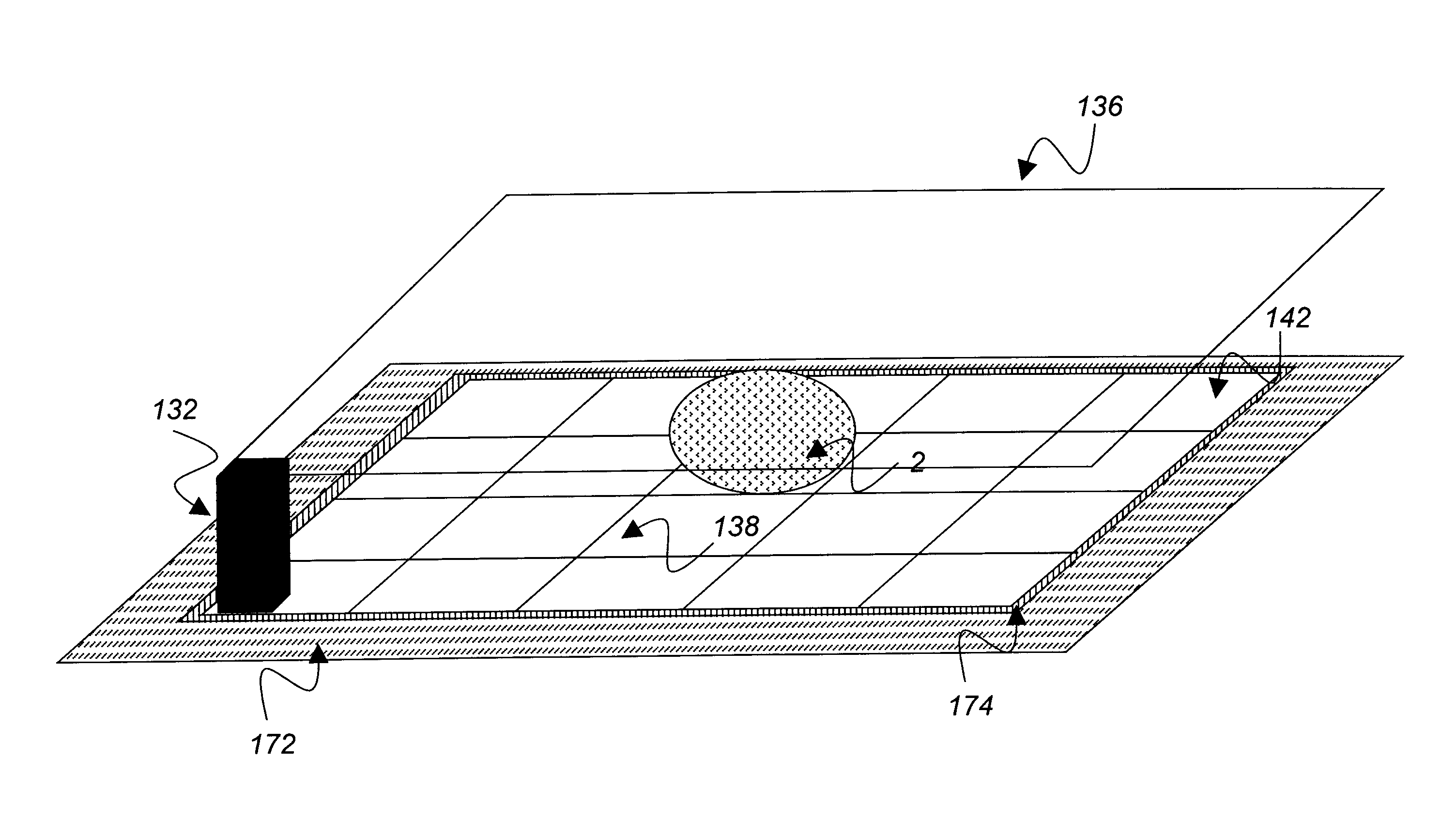
[0126]FIG. 9 shows the invention illustrating a means by which the droplet shapes previously described may be achieved using such an AM-EWOD system. FIG. 9a shows a grid illustrating part of such an array 50 of an AM-EWOD system. Elements that are colored black 52 represent those EWOD elements that are activated on the array, and the others remain non-activated. These two regions correspond to two of the substantially hexagonal droplets illustrated in the example FIG. 4b for example (third droplet not shown). The droplet shape is referred to as substantially hexagonal because a fluid droplet present in this region will adopt a broadly hexagonal shape as shown in FIG. 4. Due to surface tension of the droplet, however, it will not adopt exactly the same shape as the electrodes, i.e., the perimeter will not follow the exact “step-shaped” pattern but rather average to a smooth line more akin to the illustrative hexagons of FIG. 4. A second activation pattern is shown in FIG. 9b. When th...
fourth embodiment
[0127]FIG. 10 illustrates the invention showing an alternative means of achieving droplet shapes. Compared to FIG. 9, FIG. 10 represents a simplified array of electrodes in which a single electrode has a fixed shape which when activated commensurately produces the full shape of the drop required. Due to the reduced number and complexity of electrodes, direct wiring to each electrode is possible and thus appropriate voltages for EWOD activation are applied directly to each electrode. For example, a first shaping electrode 60 may have a fixed shape that commensurately shapes a first droplet when activated corresponding to the left hand droplet 2 of FIG. 4b, and track 66 provides connection to an external electrical supply. A second shaping electrode 62 may be provided and may have a fixed shape that commensurately shapes a second droplet when activated corresponding to the middle droplet 16a of FIG. 4b. Additional electrodes may be provided to shape additional droplets in comparable m...
PUM
| Property | Measurement | Unit |
|---|---|---|
| Magnetic field | aaaaa | aaaaa |
| Shape | aaaaa | aaaaa |
| Area | aaaaa | aaaaa |
Abstract
Description
Claims
Application Information
 - R&D
- Intellectual Property
- Life Sciences
- Materials
- Tech Scout
- Unparalleled Data Quality
- Higher Quality Content
- 60% Fewer Hallucinations
Browse by: Latest US Patents, China's latest patents, Technical Efficacy Thesaurus, Application Domain, Technology Topic, Popular Technical Reports.
© 2025 PatSnap. All rights reserved.Legal|Privacy policy|Modern Slavery Act Transparency Statement|Sitemap|About US| Contact US: help@patsnap.com


