This helps you quickly interpret patents by identifying the three key elements:
Problems solved by technology
Method used
Benefits of technology
Benefits of technology
The patent aims to use circular vortices to reduce mode coupling in optical fibers, which can help to improve the quality of received digital signals without the need for complex electronic processing. This can lead to lower power consumption and reduced latency.
Problems solved by technology
The wavelength division multiplexing technology (known as WDM) has allowed to increase the transmission capacity over a mono-mode optical fiber, but this could be not enough to satisfy the considerable increase of the required bandwidth.
This technique has the disadvantage to require at the reception side a complex electronic processing of the digital signal, thus requiring high performance processors, which consume high power values.
Moreover, the use of a complex electronic processing has the disadvantage of increasing the latency, which could be unacceptable in some applications, such as for example in metropolitan telecommunications networks.
Method used
Image
Click on the blue label to locate the original text in one second.
Reading with bidirectional positioning of images and text.
Examples
example 1
[0057]In this series of examples the value of the radial index m is set and only the value of the angular index l is changed. Moreover, it is selected at the transmission side (that is at the input facet, or face, of the multi-mode optical fiber) only one circular vortex for equal values of the radial index m and of the angular index l.
example 1.1
[0058]Set the value of the radial index to m=1, and then select the values of the angular index to l=0, 1, 2, 3, 4 and thus the circular vortices have a propagation constant β which is, to a first approximation, proportional to the value 2*1+l+1=l+3: in this case the circular vortices have different propagation constants β because they are, to a first approximation, proportional to the values 3, 4, 5, 6, 7. Moreover, the circular vortices CVl1(rt,+) are chosen (for the same value of l), that is having a right circular polarization and a clockwise screw direction.
[0059]Therefore in this example it is possible to inject at the transmission side five modes at the input facet of the multi-mode optical fiber which are the following five circular vortices with a right circular polarization and a clockwise screw direction:[0060]CV01(rt,+), CV11(rt,+), CV21(rt,+), CV31(rt,+), CV41(rt,+)
[0061]It is observed that during the propagation along the multi-mode optical fiber it is possible to have...
example 1.2
[0068]This example is analogous to example 1.1 (m=1, l=0, 1, 2, 3, 4), with the difference that the circular vortices CV11(lt,−) are chosen (for a determined value of l), that is with a left circular polarization and a counterclockwise screw direction.
[0069]Therefore in this example it is possible to inject at the transmission side five modes at the input facet of the multi-mode optical fiber which are the following five circular vortices:[0070]CV01(lt,−), CV11(lt,−), CV21(lt,−), CV31(lt,−), CV41(lt,−)
[0071]Analogously to what has been explained in the example 1.1, during the propagation along the multi-mode optical fiber it is possible to have a power exchange between the circular vortices CV01(lt,−), CV11(lt,−), CV21(lt,−), CV31(lt,−), CV41(lt,−), and the respective opposite circular vortices CV01(rt,+), CV11(rt,+), CV21(rt,+), CV31(rt,+), CV41(rt,+).
PUM
Abstract
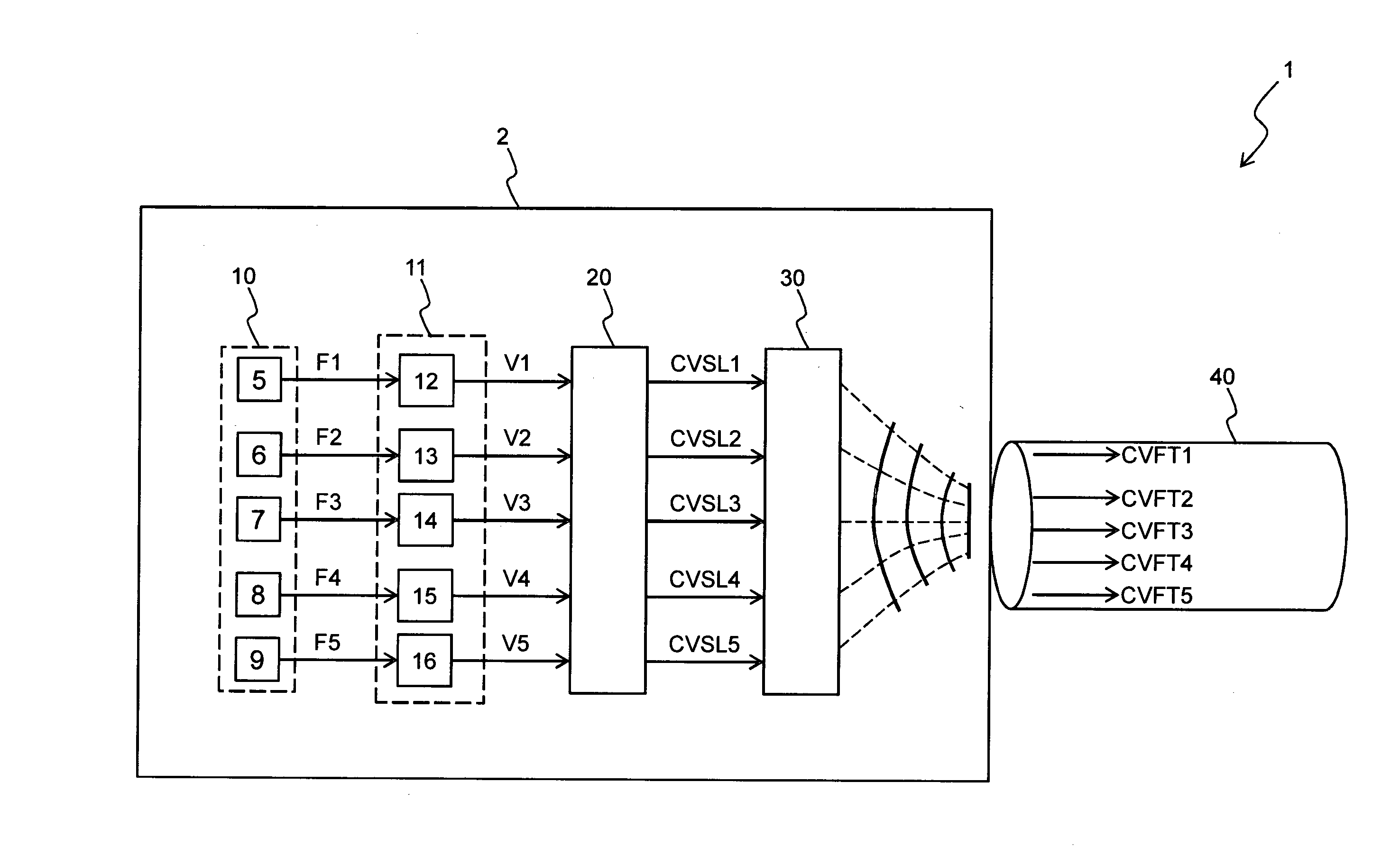
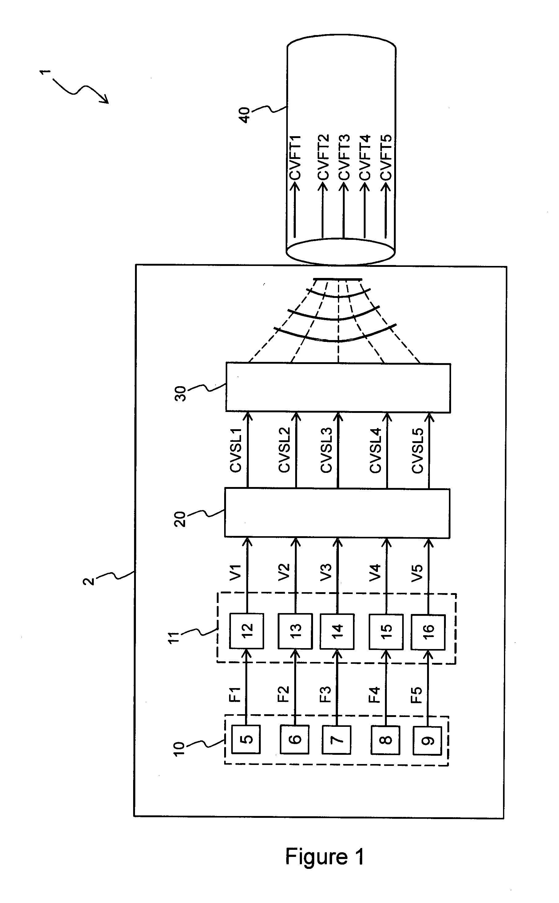
An optical communicationsystem is disclosed. The optical communicationsystem comprises an optical transmitter and a substantially circular multi-mode optical fiber. The optical transmitter comprises a generator of at least two free space circular vortices and comprises an optical element configured to receive the at least two free space circular vortices and to couple them to an input facet of the optical fiber. The optical fiber is configured to receive at the input facet the at least two free space circular vortices and is configured to generate therefrom at least two corresponding guided circular vortices having respective propagation constants, wherein the values of the propagation constants at a defined frequency are different each other.
Description
BACKGROUND[0001]1. Technical Field[0002]The present invention generally relates to the field of the communication over an optical fiber. More in particular, the present invention concerns a communication system over a multi-mode optical fiber by means of the selection of a suitable sub-set of modes.[0003]2. Description of the Related Art[0004]An optical fiber is capable to provide a high bandwidth and thus it allows the transmission of digital information at high bit rates.[0005]The wavelength division multiplexing technology (known as WDM) has allowed to increase the transmission capacity over a mono-mode optical fiber, but this could be not enough to satisfy the considerable increase of the required bandwidth.[0006]An optical fiber with circular symmetry is capable of supporting a plurality of propagation modes and thus is referred as multi-mode optical fiber. The propagation modes are obtained by means of the solution of the Maxwell equations in the optical fiber, taking into acc...
Claims
Application Information
Patent Timeline
Application Date:The date an application was filed.
Publication Date:The date a patent or application was officially published.
First Publication Date:The earliest publication date of a patent with the same application number.
Issue Date:Publication date of the patent grant document.
PCT Entry Date:The Entry date of PCT National Phase.
Estimated Expiry Date:The statutory expiry date of a patent right according to the Patent Law, and it is the longest term of protection that the patent right can achieve without the termination of the patent right due to other reasons(Term extension factor has been taken into account ).
Invalid Date:Actual expiry date is based on effective date or publication date of legal transaction data of invalid patent.
IPC IPC(8): H04B10/2581H04J14/04
CPCH04J14/04H04B10/2581G02B6/4206
InventorMARTELLI, PAOLOGATTO, ALBERTOMARTINELLI, MARIO

