Aircraft comprising a distributed electric power unit with free wheels

a distributed electric power unit and free wheel technology, applied in the direction of dynamo-electric converter control, depending on power plant type, electric devices, etc., can solve the problems of aircraft and its crew being lost, requiring a relatively large physical size, and not offering optimal safety, so as to reduce the physical size, increase the reliability of the transmission chain, and reduce the size of each electric motor element.

Active Publication Date: 2014-07-24
CHANTRIAUX ERIC +1
View PDF2 Cites 35 Cited by
  • Summary
  • Abstract
  • Description
  • Claims
  • Application Information

AI Technical Summary

Benefits of technology

[0020]Given that the distributed electromagnetic transmission unit is in direct connection with the rotating shaft, the mechanical systems used until now are completely eliminated, thereby reducing the physical size in relation to the motor units that are familiar from the prior art and considerably increasing the reliability of the transmission chain. Furthermore, the stacked architecture of the electric motor elements associated with the judicious integration of freewheeling ...

Problems solved by technology

In summary, the aircraft and its crew may be lost in the event of the failure of the mechanical reduction gear.
The output shaft from each engine is offset from the airscrew shaft, however, and a complex system of pulleys and clutches ensures the transfer of energy.
Not only does this system of propulsion necessitate a relatively large physical size, because the engine assembly is over-dimensioned for the envisaged redundancy, but it also does not offer optimal safety in the event of the failure of the pulleys and the clutches.
Here again, this pro...

Method used


Image

  • Aircraft comprising a distributed electric power unit with free wheels
  • Aircraft comprising a distributed electric power unit with free wheels
  • Aircraft comprising a distributed electric power unit with free wheels

Examples


Embodiment Construction

[0054]The propulsion device according to the invention is applicable primarily to redundant distributed electric propulsion, applied to aircraft having rotary wings (helicopters) or fixed wings (airplanes), piloted or not (drones), comprising one or a plurality of airscrews and / or one or a plurality of rotors that are caused to rotate by at least one shaft.

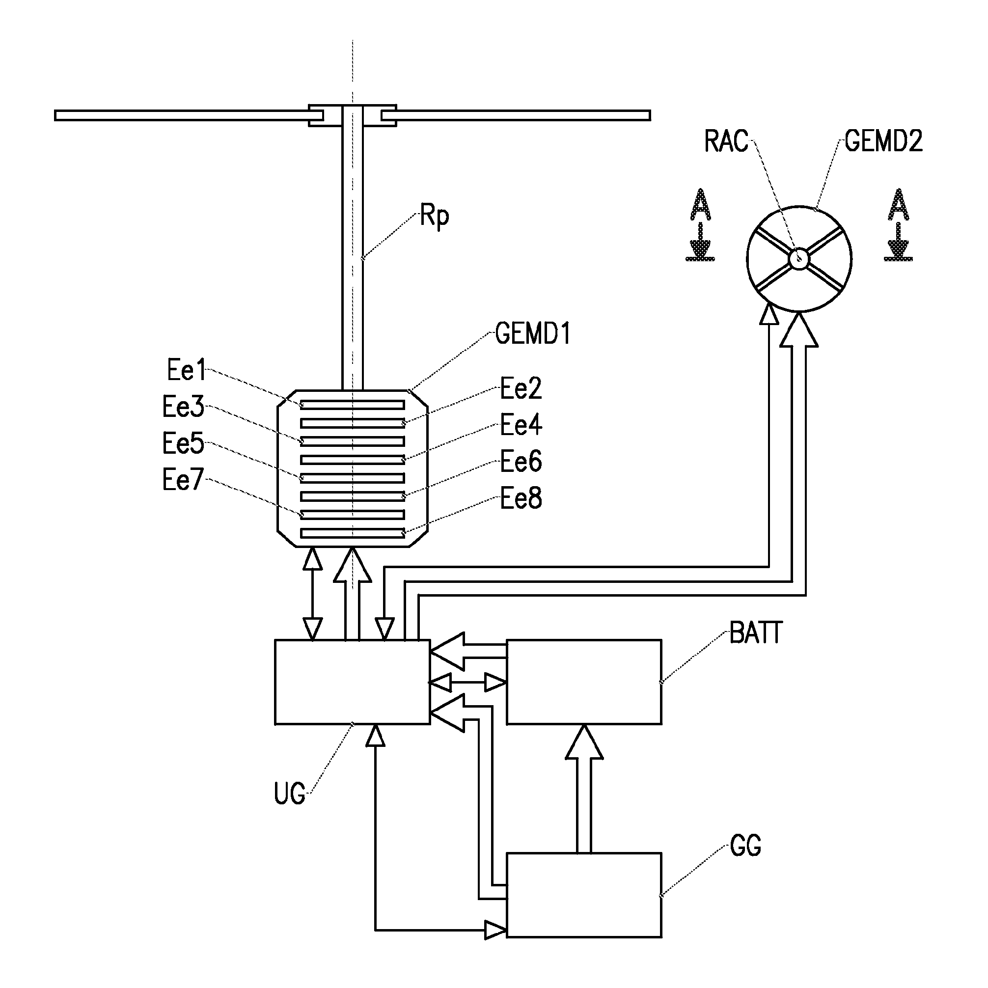
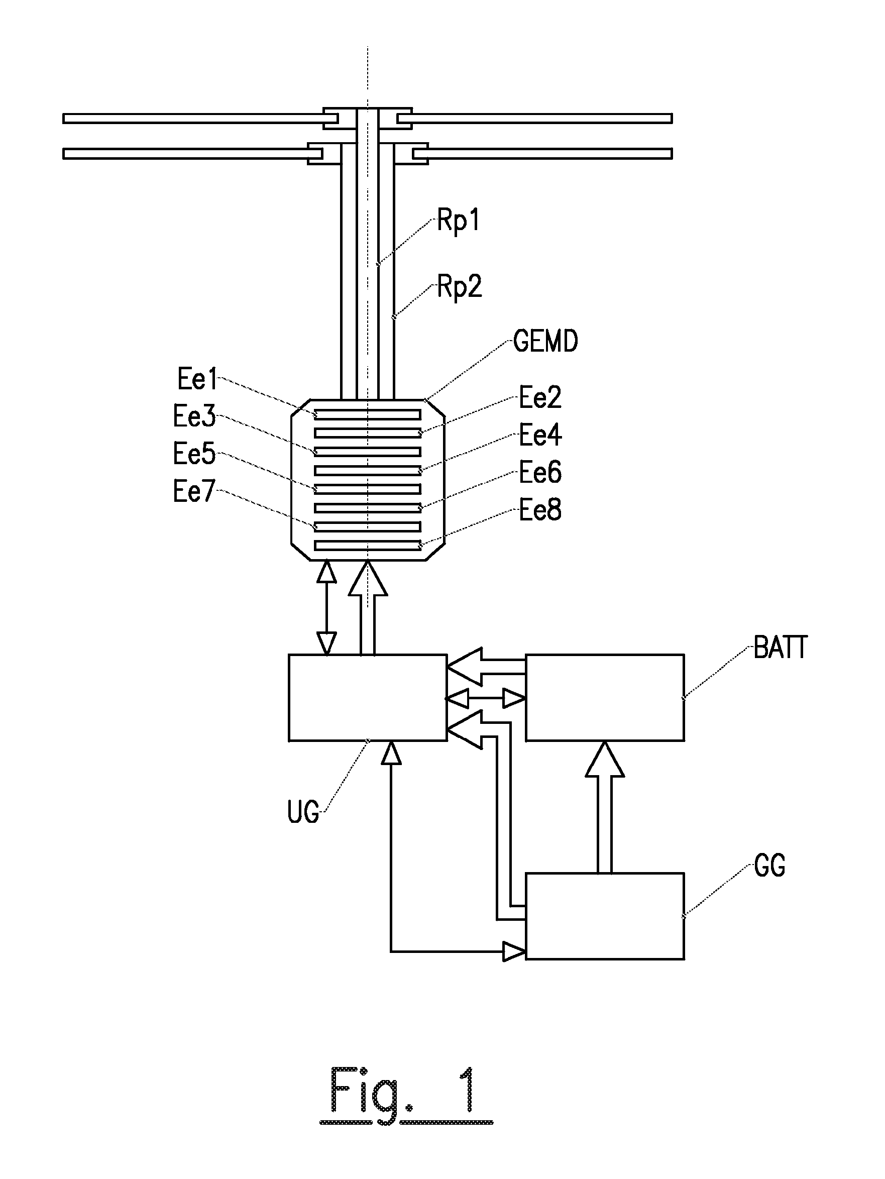
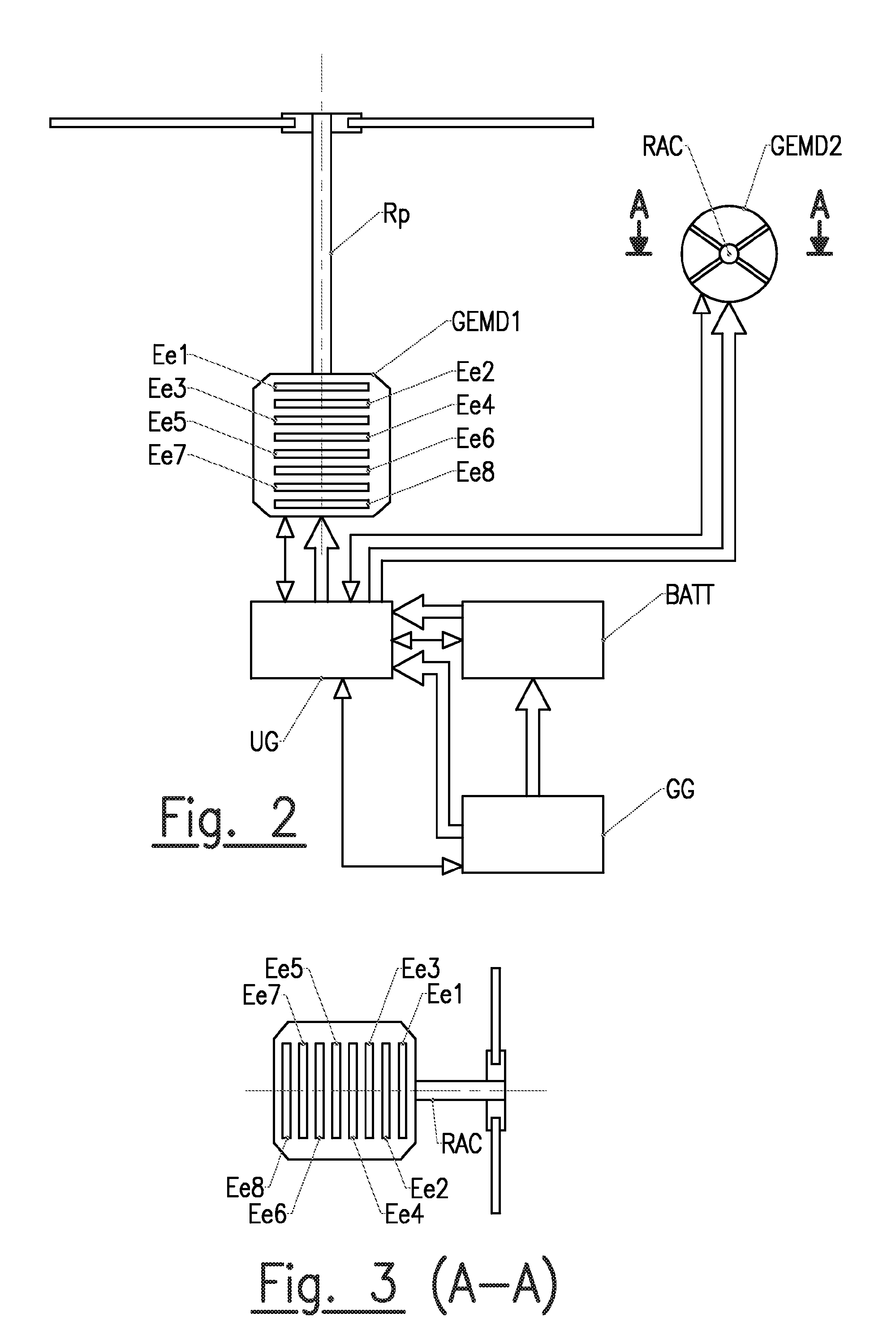
[0055]According to the invention, an electromagnetic transmission unit GEMD causes at least one rotor shaft to rotate at a variable or constant speed. In the example in FIG. 1, the electromagnetic transmission unit GEMD causes two coaxial rotors Rp1, Rp2 of a helicopter to rotate. In the example shown in FIGS. 2 and 3, an electromagnetic transmission unit GEMD1 causes the main rotor Rp of a helicopter to rotate, and another electromagnetic transmission unit GEMD2 causes the anti-torque tail rotor (RAC) to rotate. In the example shown in FIG. 4, the electromagnetic transmission unit GEMD causes the shafts on which coaxial airscrews...


PUM


Abstract

The invention relates to a rotary- or fixed-wing aircraft comprising one or more rotors and/or one or more propellers, in which the rotor(s) and/or propeller(s) are rotated at a variable or constant speed by at least one shaft (Rp1, Rp2, Rp, RAC, H), and the aircraft includes a power unit (GEMD) configured to propel and/or lift the aircraft by rotating the shaft. The aircraft is characterised in that: the power unit (GEMD) is a distributed electric power unit formed by multiple stacked electric power elements (Ee1, Ee2, Een), each element being adapted to confer, on the rotation shaft (Rp1, Rp2, Rp, RAC, H), a fraction of the total power necessary in order to propel and/or lift the aircraft; the distributed electric power unit (GEMD) is in direct engagement with the rotation shaft (Rp1, Rp2, Rp, RAC, H), with no movement transmission mechanism being inserted between the unit and the shaft; each electric power element (Ee1, Ee2, Een) is directly connected to the rotation shaft (Rp1, Rp2, Rp, RAC, H) and comprises at least one fixed stator (St), at least one moving rotor (Rt) and at least one mechanical or electromagnetic free wheel (RI) in direct engagement with the rotation shaft, said moving rotor (Rt) co-operating with the free wheel (RI) such as to be coupled to the rotation shaft during normal operation of the electric power unit (Ee1, Ee2, Een) and to be disconnected from the shaft in the event of the failure of the electric power element; and the rotation shafts of the moving rotors (Rt), the free wheels (RI) and the rotation shaft (Rp1, Rp2, Rp, RAC, H) are coaxial.

Description

TECHNICAL FIELD OF THE INVENTION[0001]The subject matter of the invention is a rotary- or fixed-wing aircraft equipped with a distributed electromagnetic transmission unit composed of a stack of electric motor elements, each producing a fraction of the total power necessary for the setting in rotation of a rotor shaft, each said electric motor element being fitted with a freewheeling unit.[0002]The invention relates to the technical field of electromagnetic power transmissions applied to aircraft having fixed wings (airplanes) or rotary wings (helicopters), regardless of whether these are piloted or not (for example: drones).STATE OF THE ART[0003]Traditional propulsion systems for aircraft generally consist of a thermal engine or turboshaft engines or turbo-fan engines and a mechanical reduction gearbox coupled to the rotor shaft. Reduction gears are currently used:[0004]in helicopters, for transmitting the mechanical torque produced by the one or more engines or turboshaft engines ...

Claims


Application Information

Patent Timeline
IPC IPC(8): B64D35/02H02P27/00H02P4/00H02P5/74
CPCB60K6/383B64C27/04B64C27/14B64D27/24B64D35/08H02K16/00H02K7/14H02K2213/06H02K2213/12Y02T50/64Y02T50/44B64D35/02H02P4/00H02P5/74H02P27/00H02K7/116B60L2200/10B60L2220/42Y02T10/64Y02T50/40Y02T50/60
Inventor CHANTRIAUX, ERICCHRETIEN, PASCAL
Owner CHANTRIAUX ERIC
Why Eureka
Try Eureka