
Nuclear fuel rod for fast reactors including metallic fuel slug coated with protective coating layer and fabrication method thereof

a technology metal fuel slugs, which is applied in the direction of nuclear elements, greenhouse gas reduction, therapy, etc., can solve the problems of limited maximum allowable operating temperature of metallic fuel for fast reactors, complicated production of nuclear fuel rods, and cracks in zirconium tubes

Active Publication Date: 2014-07-24
KOREA ATOMIC ENERGY RES INST +1
View PDF3 Cites 7 Cited by
  • Summary
  • Abstract
  • Description
  • Claims
  • Application Information

AI Technical Summary

Benefits of technology

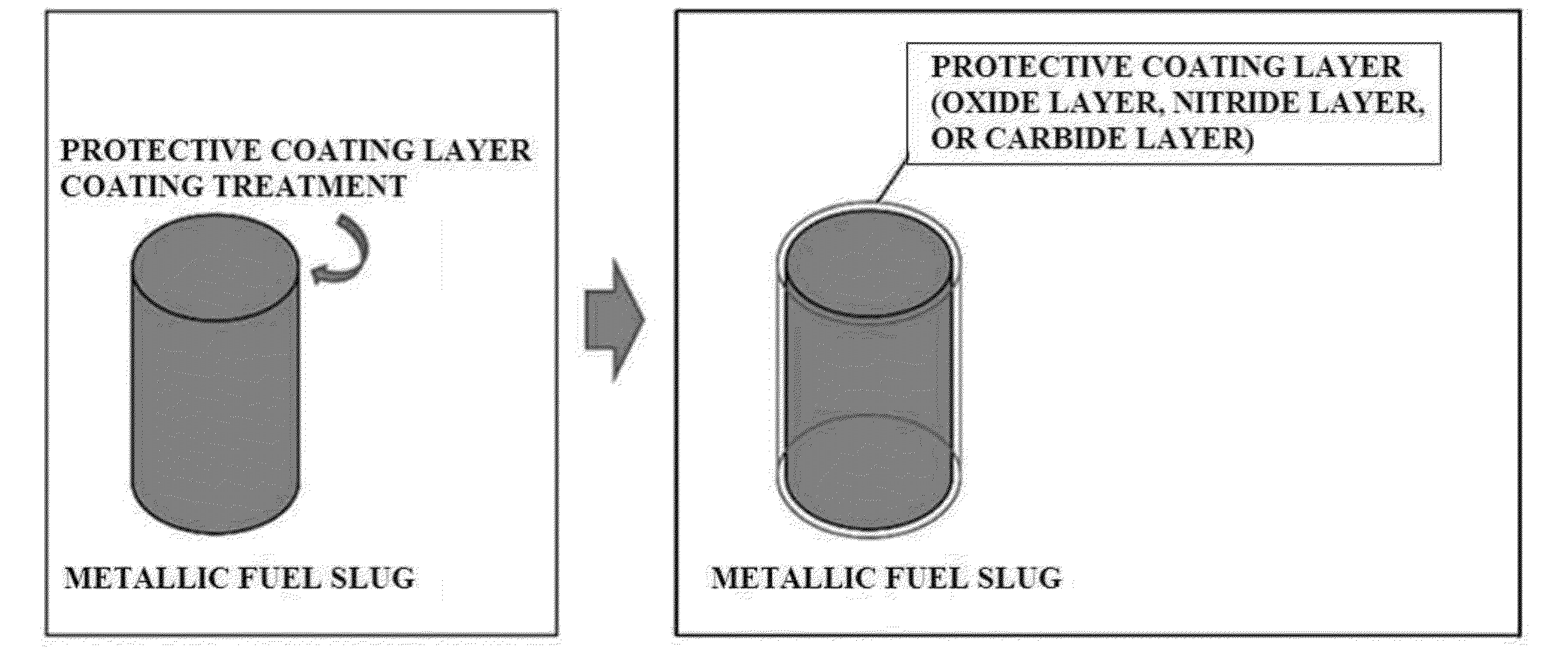
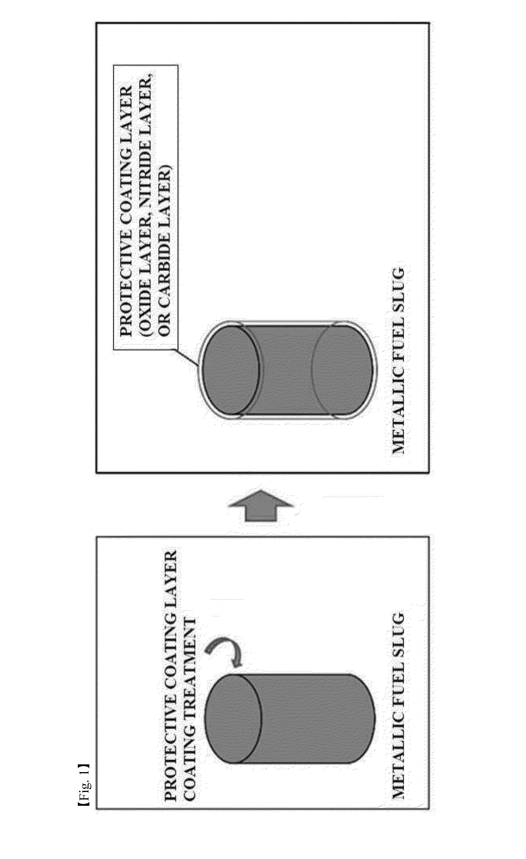
The present invention is about a metallic fuel slug used in a nuclear fuel rod for fast reactors. The metallic fuel slug has a surface coated with a single protective coating layer to improve its performance. The protective coating layer can be formed by oxidation, nitridation, or caburization of the metallic fuel slug. A nuclear fuel rod for fast reactors can also be fabricated by coating the surface of a metallic fuel slug with a single protective coating layer, sealing a cladding tube after introducing the coated slug into the cladding tube, and providing a method of fabricating a nuclear fuel rod for fast reactors by coating the surface of metallic fuel powder with a single protective coating layer, preparing a metallic fuel slug, and sealing a cladding tube after introducing the slug into the cladding tube. The technical effect of this patent is to improve the performance of metallic fuel slugs used in nuclear fuel rods for fast reactors.

Problems solved by technology

Thus, the maximum allowable burnup and the maximum allowable operating temperature of the metallic fuel for fast reactors may be limited [J. Nucl. Mater., 204 (1993) p.
Since the technique of GE essentially requires the introduction of an additional process, the production of the nuclear fuel rod may not only be complicated, but considerable additional costs may also be required.
However, cracks may occur in the zirconium tube.
As a result, the lifetime of the cladding tube may decrease due to the deterioration of the soundness thereof.
Thus, there may be limitations in attaching the functional material for preventing interdiffusion to the inside of the thin and long tube, and treatment costs may be high.

Method used


Image

  • Nuclear fuel rod for fast reactors including metallic fuel slug coated with protective coating layer and fabrication method thereof
  • Nuclear fuel rod for fast reactors including metallic fuel slug coated with protective coating layer and fabrication method thereof
  • Nuclear fuel rod for fast reactors including metallic fuel slug coated with protective coating layer and fabrication method thereof

Examples


example 1

Fabrication 1 of Nuclear Fuel Rod for Fast Reactors Having Oxide Layer Formed on Surface

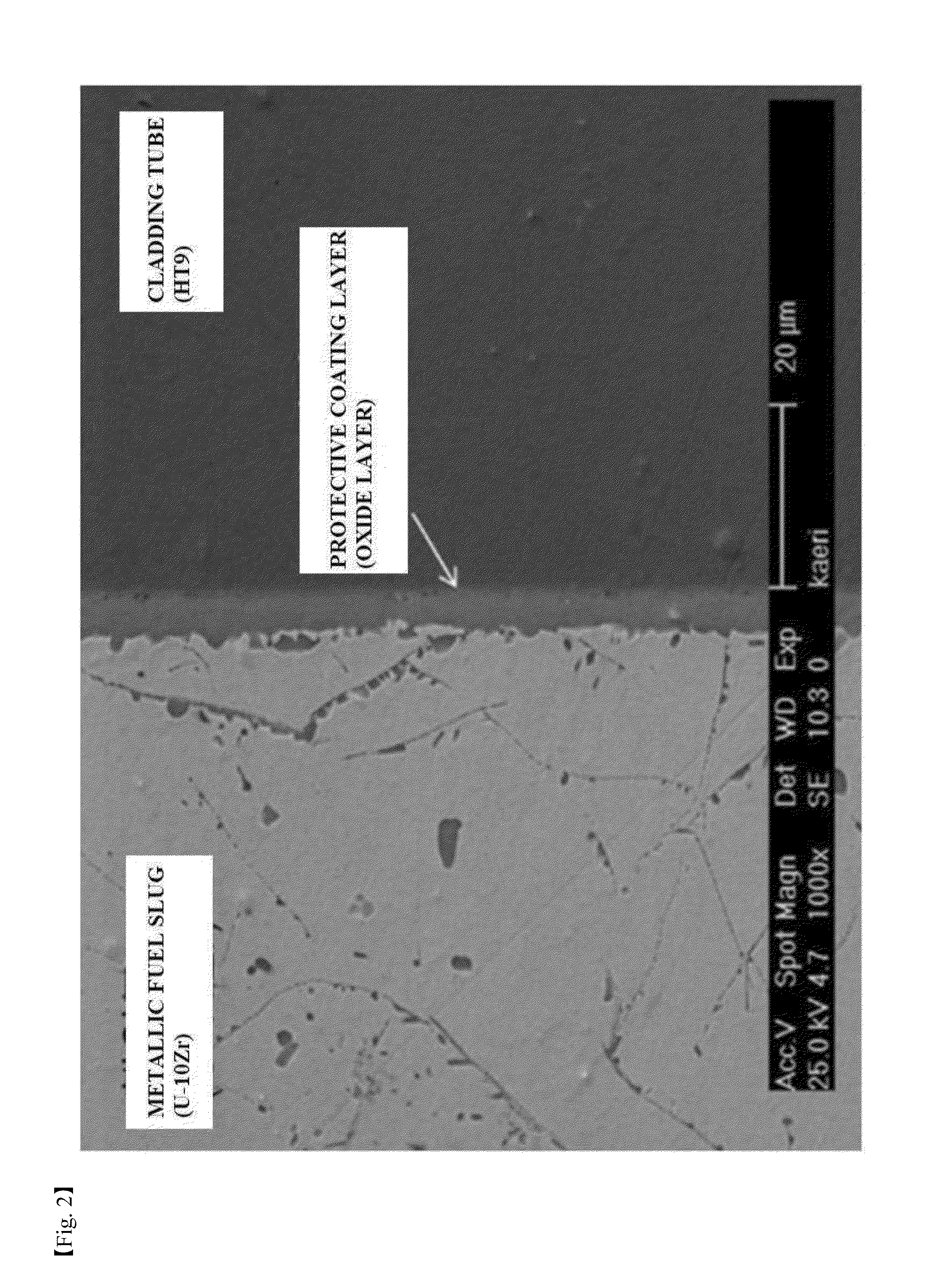
[0070]An oxide layer was formed on a surface of a metallic fuel slug by heat treating the metallic fuel slug formed of U-10Zr, a nuclear fuel material, at a temperature of 600° C. and a pressure of 5 atm for 2 hours in an argon gas atmosphere containing 20% oxygen. Then, the heat-treated metallic fuel slug was put into a HT9 (12Cr-1Mo) cladding tube to fabricate a nuclear fuel rod for fast reactors.

example 2

Fabrication 2 of Nuclear Fuel Rod for Fast Reactors Having Oxide Layer Formed on Surface

[0071]An oxide layer was formed on a surface of a metallic fuel slug by heat treating the metallic fuel slug formed of U-10Zr, a nuclear fuel material, at a temperature of 150° C. and a pressure of 1 atm for 1 hour in an air atmosphere. Then, the heat-treated metallic fuel slug was put into a HT9 (12Cr-1Mo) cladding tube to fabricate a nuclear fuel rod for fast reactors.

Example 3

Fabrication 3 of Nuclear Fuel Rod for Fast Reactors Having Oxide Layer Formed on Surface

[0072]An oxide layer was formed on a surface of a metallic fuel slug by heat treating the metallic fuel slug formed of U-10Zr, a nuclear fuel material, at a temperature of 300° C. and a pressure of 1 atm for 1 hour in an air atmosphere. Then, the heat-treated metallic fuel slug was put into a HT9 (12Cr-1Mo) cladding tube to fabricate a nuclear fuel rod for fast reactors.

example 4

Fabrication 4 of Nuclear Fuel Rod for Fast Reactors Having Oxide Layer Formed on Surface

[0073]An oxide layer was formed on a surface of a metallic fuel slug by dipping the metallic fuel slug formed of U-10Zr, a nuclear fuel material, in a hydrochloric acid solution at 50° C. for 2 hours. Then, the metallic fuel slug was put into a HT9 (12Cr-1Mo) cladding tube to fabricate a nuclear fuel rod for fast reactors.


PUM


Abstract

Provided are a nuclear fuel rod for fast reactors that includes a metallic fuel slug coated with a protective coating layer and a fabrication method thereof. The nuclear fuel rod for fast reactors that includes a surface treated metallic fuel slug and a cladding tube according to the present invention has an excellent effect of stabilizing components of the metallic fuel slug and fission products or impurities, because the interdiffusion between the metallic fuel slug and the cladding tube does not occur. Also, since the uniform coating on the surface of the metallic fuel slug may be facilitated and fabrication costs may be significantly reduced in comparison to a typical technique of using a functional material for preventing the interdiffusion at an inner surface of the cladding tube, it may be suitable for fabricating the nuclear fuel rod for fast reactors.

Description

CROSS-REFERENCES TO RELATED APPLICATION[0001]This patent application claims the benefit of priority from Korean Patent Application No. 10-2013-0005989 filed on Jan. 18, 2013, and Korean Patent Application No. 10-2013-0110624 filed on Sep. 13, 2013, the contents of which are incorporated herein by reference.BACKGROUND OF THE INVENTION[0002]1. Field of the Invention[0003]The present disclosure relates to a nuclear fuel rod for fast reactors that includes a metallic fuel slug coated with a protective coating layer and a fabrication method thereof.[0004]2. Description of the Related Art[0005]The present invention relates to a process for improving the performance of nuclear fuel for reactors, and more particularly, to a technique that stabilizes components of a metallic fuel slug and fission products or impurities through the stabilization of surfaces of the metallic fuel slug and metallic fuel powder by a surface treatment.[0006]Nuclear fuel in fast reactors is designed in various type...

Claims


Application Information

Patent Timeline
IPC IPC(8): G21C3/04
CPCG21C3/20G21C2003/047G21C21/02G21C3/047Y02E30/30G21C1/02G21C3/04G21C3/60
Inventor LEE, CHAN BOCKKIM, JUN HWANBAEK, JONG-HYUKCHEON, JIN-SIKLEE, BYOUNGOONKIM, KI HWANKIM, SUNG-HOKIM, JUNEHYUNGOH, SEOK-JINKO, YOUNG-MOWOO, YOON-MYEONGYANG, SEONG WOO
Owner KOREA ATOMIC ENERGY RES INST
Learn More