Exhaust diffuser and method for manufacturing an exhaust diffuser

a technology of exhaust diffuser and exhaust diffuser, which is applied in the direction of machines/engines, stators, liquid fuel engines, etc., can solve the problems of reducing the efficiency reducing the number of supporting struts, and reducing the amount of supporting struts. , to achieve the effect of maintaining the structural stability of the exhaust diffuser and reducing the amount of supporting struts

a technology of exhaust diffuser and exhaust diffuser, which is applied in the direction of machines/engines, stators, liquid fuel engines, etc., can solve the problems of reducing the efficiency reducing the number of supporting struts, and reducing the amount of supporting struts. , to achieve the effect of maintaining the structural stability of the exhaust diffuser and reducing the amount of supporting struts

US20140205448A1Active Publication Date: 2014-07-24SIEMENS ENERGY GLOBAL GMBH & CO KG

Image

  • Exhaust diffuser and method for manufacturing an exhaust diffuser
  • Exhaust diffuser and method for manufacturing an exhaust diffuser
  • Exhaust diffuser and method for manufacturing an exhaust diffuser

Examples


Embodiment Construction

[0073]The illustration in the drawing is schematically provided.

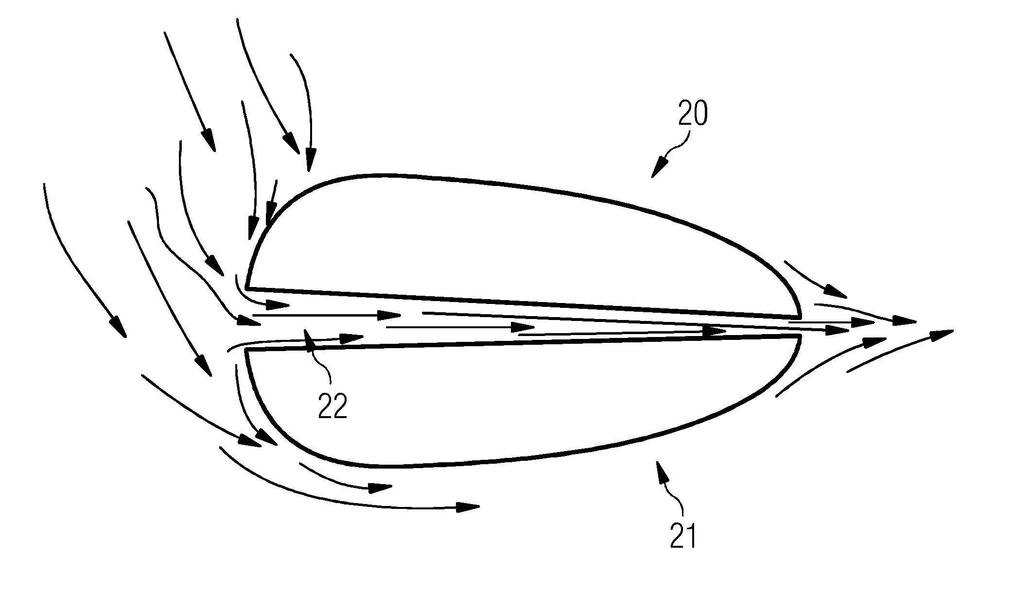
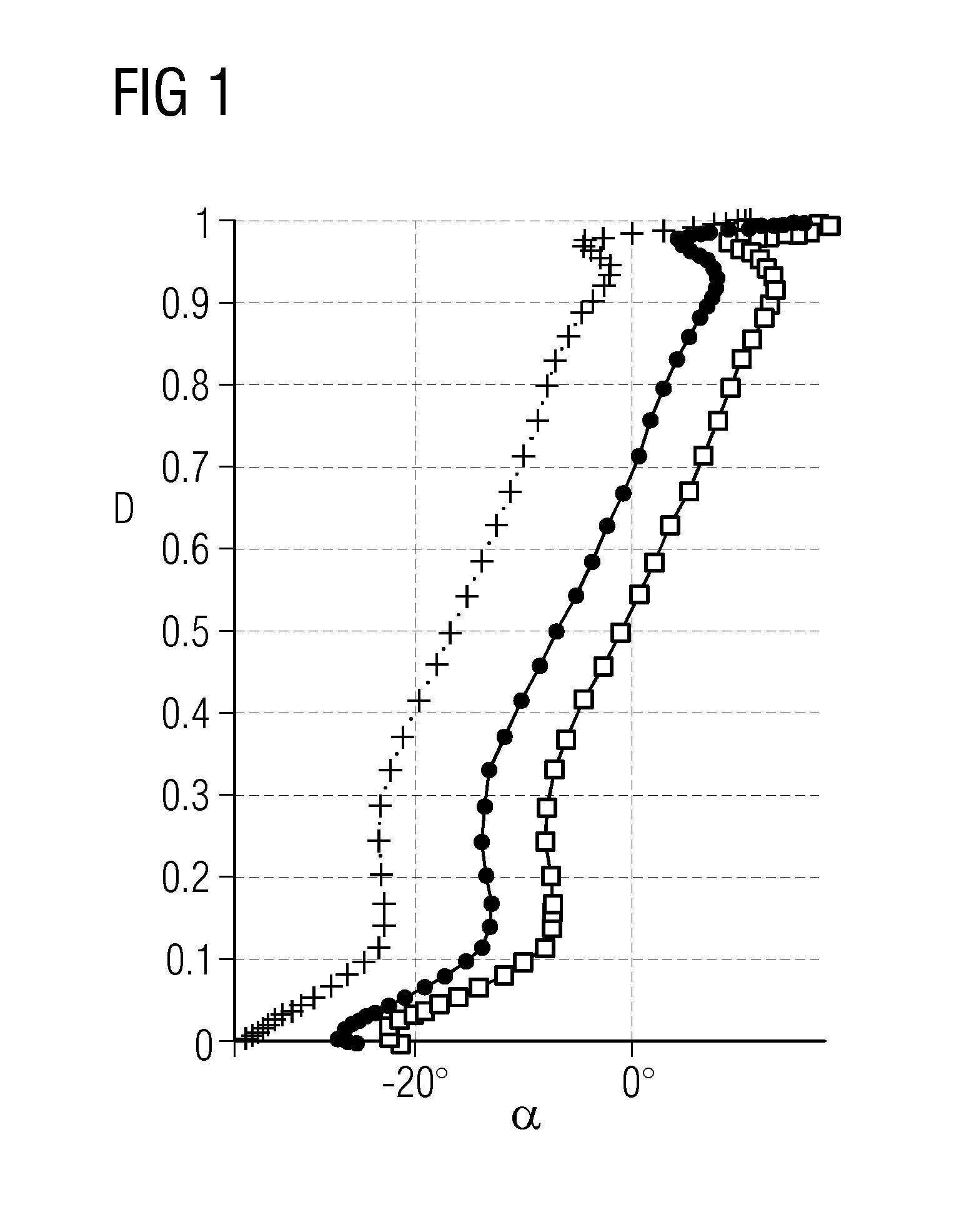
[0074]FIG. 1 shows the flow angle a of the fluid flow entering an exhaust diffuser versus the normalized distance D from the outer surface of its inner member to the inner surface of its outer member for a low, middle and high capacity of a torque-generating gas turbine. For a middle capacity the flow angle varies from −27 degree at the outer surface of the inner member of the exhaust diffuser to approximately 10 degree at the inner surface of the outer member of the exhaust diffuser. The mean flow angle is approximately 5 degree, which allows for good diffuser recovery.

[0075]In particular, near the outer surface and the inner surface the flow angle gradient is quite extreme. Accordingly, it may be advantageous to treat these end wall regions differently.

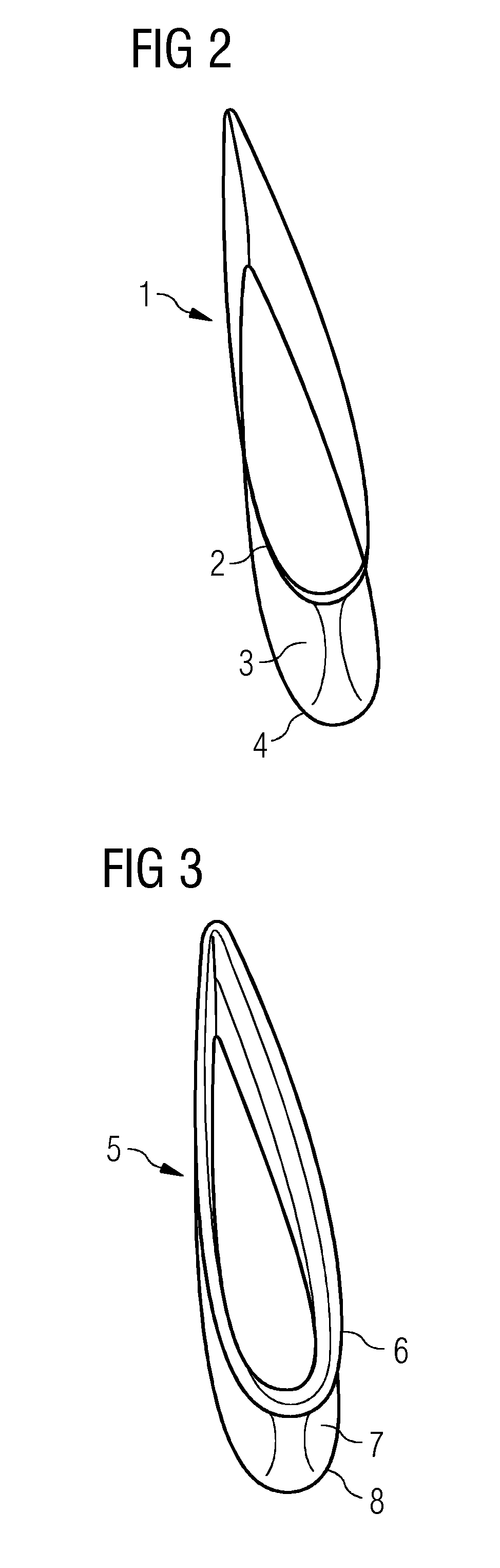
[0076]FIG. 2 shows a prismatic supporting strut 1 according to the state of the art comprising an inner section 2, a middle section 3, and an outer section 4 all having...


PUM


Abstract

An exhaust diffuser and method for manufacturing an exhaust diffuser is provided. An exhaust diffuser for a torque-generating turbine, in particular a torque-generating gas turbine is provided herein. The exhaust diffuser having an inner member, the inner member having an outer surface and an outer member having an inner surface, the inner member and the outer member forming an annular channel, at least a first supporting strut connecting the inner member and the outer member, the first supporting strut extending essentially radially from the inner surface to the outer surface, the first supporting strut having a middle section having a first airfoil and an outer section having a second airfoil, and the second airfoil differing from the first airfoil in shape to be able to handle a higher range of angle of attack. Furthermore, it is described a method for manufacturing an exhaust diffuser.

Description

CROSS REFERENCE TO RELATED APPLICATIONS[0001]This application is the US National Stage of International Application No. PCT / EP2012 / 065054 filed Aug. 1, 2012, and claims the benefit thereof. The International Application claims the benefit of European Application No. 11178144 filed Aug. 19, 2011. All of the applications are incorporated by reference herein in their entirety.FIELD OF INVENTION[0002]The present invention relates to the field of torque-generating turbines, in particular torque-generating gas turbines. More particularly, the invention relates to an exhaust diffuser for a torque-generating turbine, in particular a torque-generating gas turbine, and a method for manufacturing an exhaust diffuser.ART BACKGROUND[0003]Torque generating turbines are rotary engines that extract energy from a fluid flow, e.g. steam flow and / or combustion gas flow, and convert it into useful work. Typically, torque-generating turbines are used to drive a generator to produce electric energy. Usua...

Claims


Application Information

Patent Timeline
24 Jul 2014
Publication
US20140205448A1
IPC
F04D19/02
CPC
F04D19/022; F05D2220/321; F01D5/145; F01D25/30; F05D2240/12; Y02T50/60
Inventors
WONG, LI SHING