
Near-surface object sensing device and sensing method

Active Publication Date: 2014-07-24
NAT TAIWAN UNIV
View PDF6 Cites 11 Cited by
  • Summary
  • Abstract
  • Description
  • Claims
  • Application Information

AI Technical Summary

Benefits of technology

The present invention provides a sensing device and method that uses magnetic sensors on a printed circuit board. This makes the device compact and energy-efficient. Additionally, the device can use a permanent magnetic material as a signal source without needing a separate power supply. The device also has a six-dimensional coordinates-calculating module that accurately calculates three-dimensional positions (x, y, z) and provides users with convenient and intuitive user interface within a near-surface space.

Problems solved by technology

The downside is that GUIs are restricted to the scope of two-dimensional display with the resolutions able to describe generic information, and the actions are usually performed through direct manipulation of the graphical elements, and thus they require configurations of keyboards, mouse and display screens as well as users' manipulation of keyboard input and mouse.
However, conventional tangible user interfaces are based on two-dimensional surface touch technology, and although the manipulation of three-dimensional interfaces by using computer vision technology or traditional electromagnetic sensing technology without a touch display screen is readily available, the computer vision technology is easily blocked and affected by occlusion and results in dead angles.
On the other hand, while low frequency electromagnetic sensing technology can avoid interference of occlusion to sense objects, portability of such technology is compromised by the object to be sensed as it would require a power supply and the heavyweight transmitter for signal processing.
Moreover, the conventional electromagnetic sensing technology also would have difficulties in recognizing tilting, hovering and rolling motions of an external magnetic object.

Method used


Image

  • Near-surface object sensing device and sensing method
  • Near-surface object sensing device and sensing method
  • Near-surface object sensing device and sensing method

Examples


Embodiment Construction

[0016]The following illustrative embodiments are provided to illustrate the disclosure of the present invention, these and other advantages and effects can be understood by persons skilled in the art after reading the disclosure of this specification. Note that the structures, proportions, sizes depicted in the accompanying figures merely serve to illustrate the disclosure of the specification to allow for comprehensive reading without a limitation to the implementation or applications of the present invention, and does not constitute any substantial technical meaning.

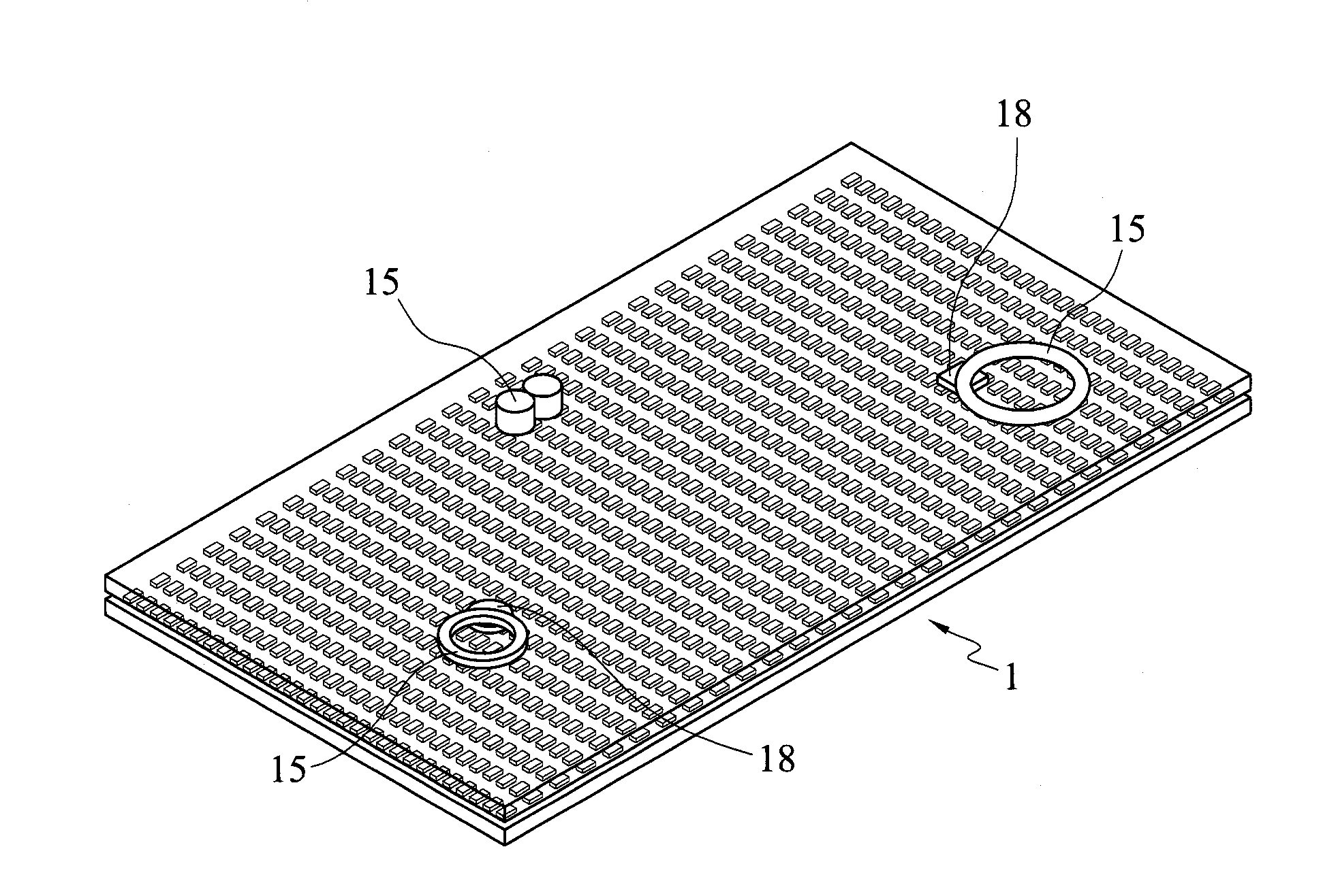
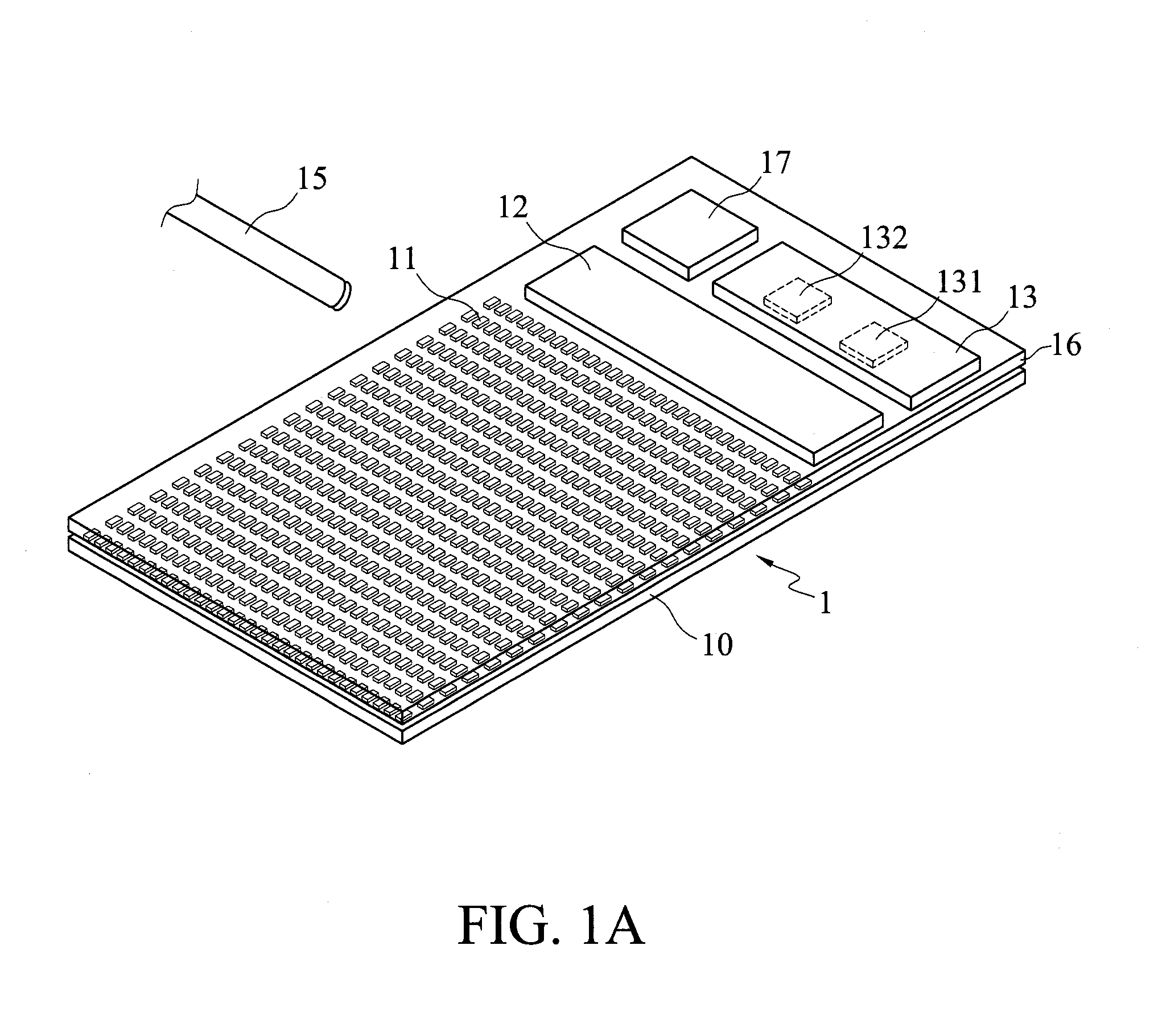
[0017]According to a first preferred embodiment of the present invention, FIG. 1A is a schematic view of the near-surface object sensing device 1, including a printed circuit board 10, a plurality of magnetic sensors 11, a multiplexer 12, and a microprocessor 13.

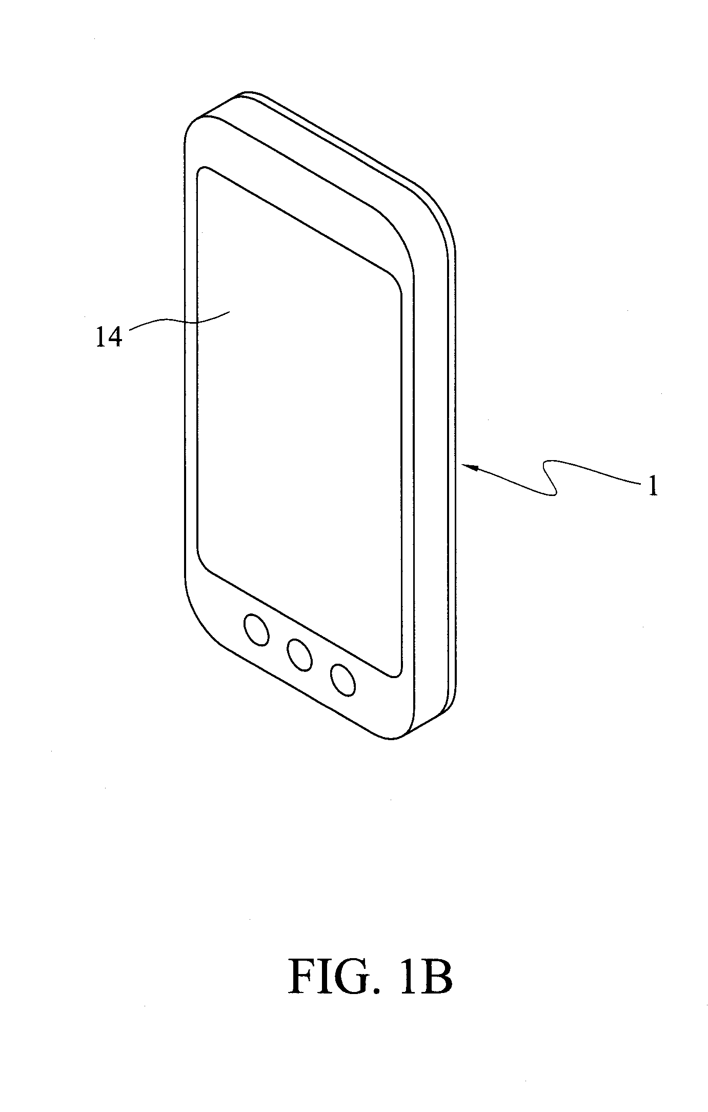
[0018]The printed circuit board 10 can be electrically connected to an external electronic device 14 which may be, for instance, a smart phone, a tablet comput...


PUM


Abstract

Disclosed is a near-surface object sensing device, including a printed circuit board, a plurality of magnetic sensors arrayed on the printed circuit board to sense the magnetic field of an external magnetic object and generate a magnetic sensing signal, a multiplexer connected to the magnetic sensors for selecting and outputting the magnetic sensing signal, and a microprocessor connected to the multiplexer for receiving the magnetic sensing signal, wherein the microprocessor includes a sampling algorithm module for converting the magnetic sensing signal into a magnetic field distribution image, and a six-dimensional coordinate-calculating module for calculating six-dimensional coordinates of the external magnetic object. The sensing device of the invention is compact, low energy consuming and can accurately provide users with a convenient and intuitive user interface with three dimensional locations and position information in a near-surface space.

Description

BACKGROUND OF THE INVENTION[0001]1. Field of the Invention[0002]The present invention relates to a technique for object sensing, and more particularly, to a near-surface object sensing device and a near-surface object sensing method.[0003]2. Description of Related Art[0004]The evolution of input interfaces and output methods of electronic devices changes with advanced technology, from the earliest pinhole plotter that was used as an input program, then the text-based user interface of using keyboard inputs and screen displays, to the recent window operating system of Graphical User Interface, GUI. A GUI represents the information and actions available to a user through graphical icons and visual indicators as opposed to text-based interfaces, typed command labels or text navigation. The downside is that GUIs are restricted to the scope of two-dimensional display with the resolutions able to describe generic information, and the actions are usually performed through direct manipulati...

Claims


Application Information

Patent Timeline
IPC IPC(8): G01B7/016
CPCG01B7/016G01B7/003G01B7/004G01D5/142G06F3/046
Inventor LIANG, RONG-HAOCHEN, BING-YUCHENG, KAI-YIN
Owner NAT TAIWAN UNIV
Features
  • Generate Ideas
  • Intellectual Property
  • Life Sciences
  • Materials
  • Tech Scout
  • Unparalleled Data Quality
  • Higher Quality Content
  • 60% Fewer Hallucinations
Learn More