Vehicle steering system

a steering system and vehicle technology, applied in electric devices, transportation and packaging, tractors, etc., can solve the problems of not being able to completely protect the driver from electric shock, not being able to continue steering operation,

Inactive Publication Date: 2014-07-31
JTEKT CORP
View PDF4 Cites 7 Cited by
  • Summary
  • Abstract
  • Description
  • Claims
  • Application Information

AI Technical Summary

Benefits of technology

[0007]An object of the invention is to provide a vehicle steering system that makes it possible to avoid a situation in which a driver receives electric shock, and to continue to provide steering assist so as to safely evacuate a vehicle, when a collision of the vehicle occurs.

Problems solved by technology

However, when a hybrid vehicle, in which the above-described electric power steering system is provided, has a collision while traveling, it is necessary to stop the supply of electric power to the electric power steering system in order to avoid a situation in which electric shock occurs due to a high voltage, for example, a situation in which a current flows to a driver via a steering mechanism.
However, when driving of vehicle wheels is stopped, it is not possible to continue to perform a steering operation, and it may not be possible to cause the vehicle to travel in a limp home mode to evacuate the vehicle.
Electric insulation may be achieved using electric control, but when a failure occurs in a control circuit or the like after the collision occurs, it is not possible to completely protect the driver from electric shock.

Method used


Image

  • Vehicle steering system
  • Vehicle steering system
  • Vehicle steering system

Examples


Embodiment Construction

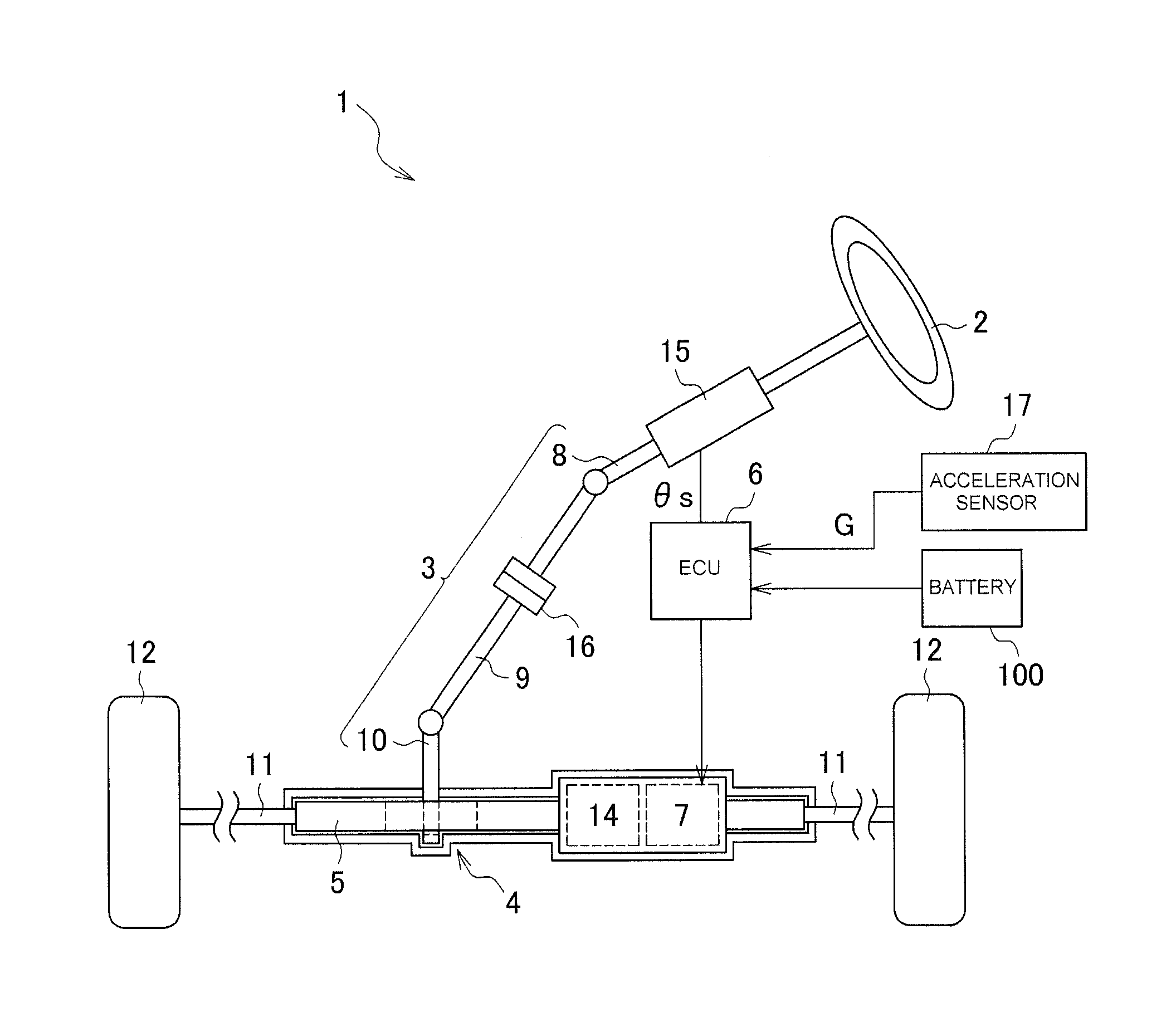
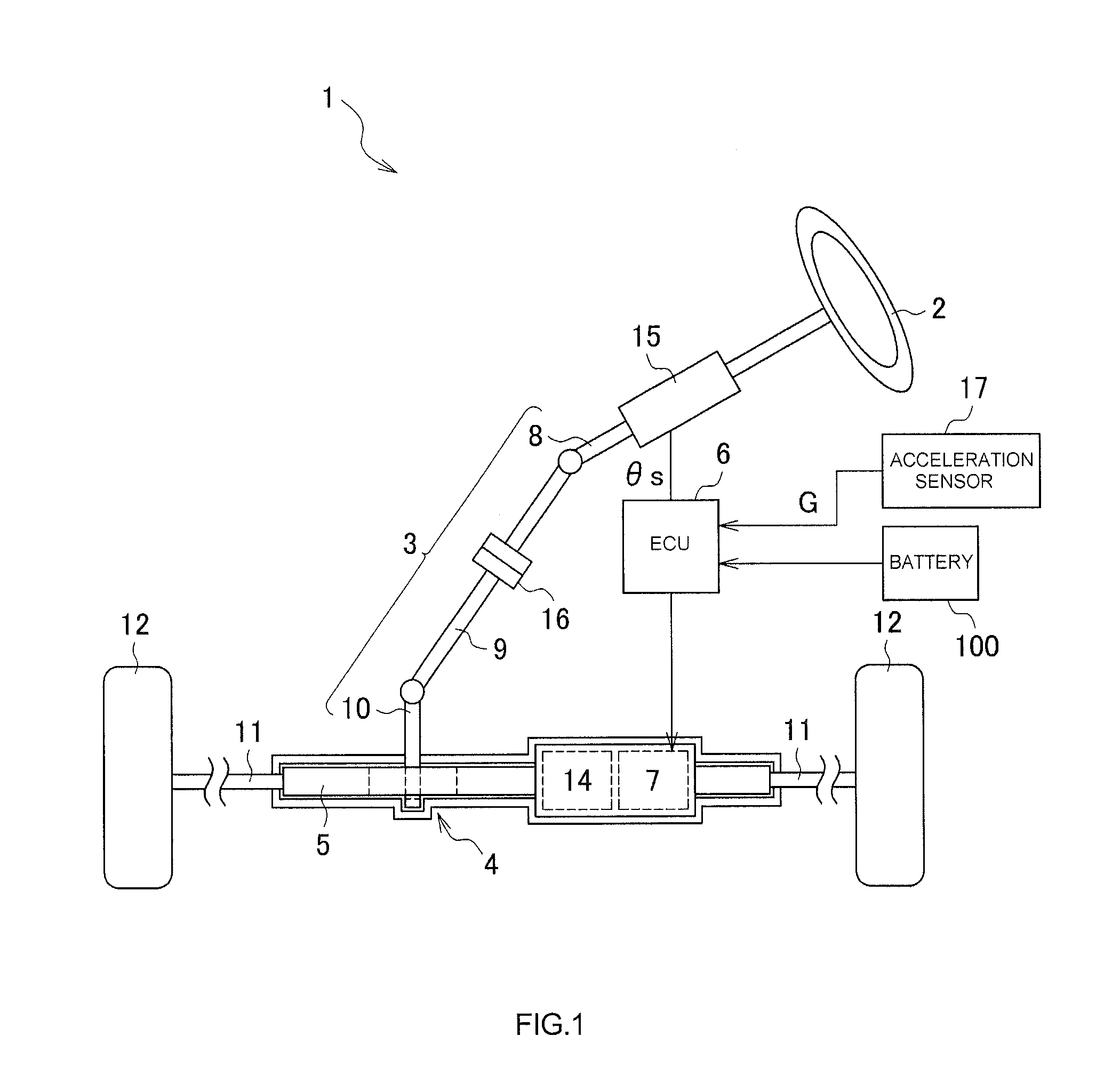
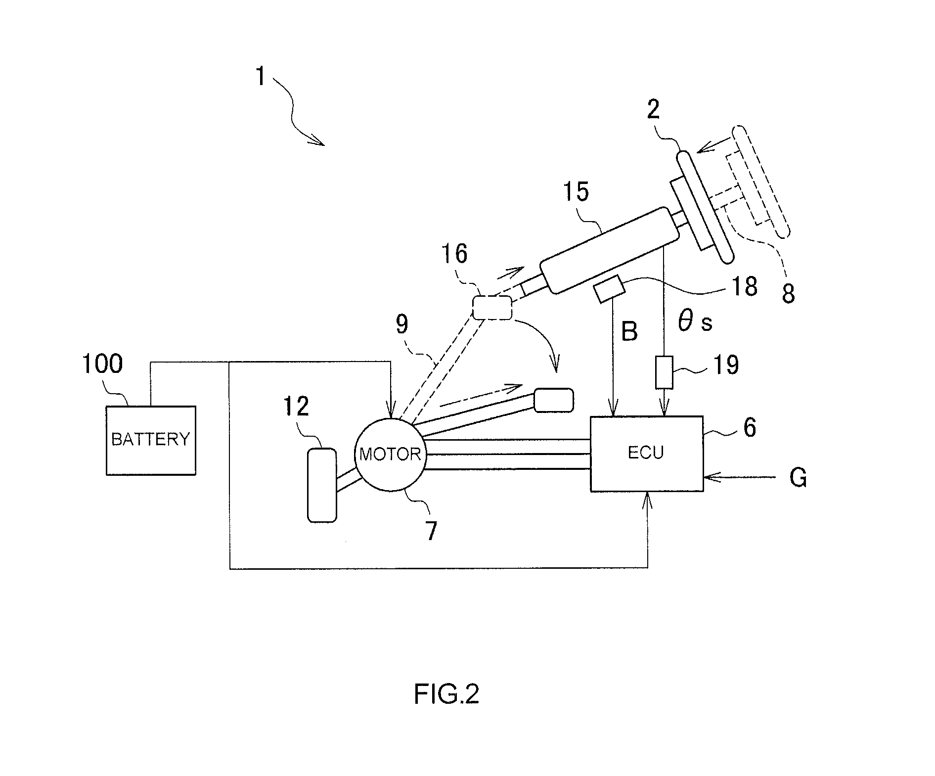
[0018]Hereinafter, a vehicle steering system provided in a vehicle according to an embodiment of the invention will be described with reference to the accompanying drawings. As shown in FIG. 1, in a vehicle steering system 1, a steering shaft assembly 3, to which a steering wheel 2 is fixed, is connected to a rack shaft 5 through a rack and pinion mechanism 4. Accordingly, rotation of the steering shaft assembly 3 due to a steering operation is converted to a reciprocating linear motion of the rack shaft 5 by the rack and pinion mechanism 4. The steering shaft assembly 3 includes a column shaft 8, an intermediate shaft 9, and a pinion shaft 10, which are connected to each other. The column shaft 8 is supported by a steering column 15 through bearings so that the column shaft 8 is rotatable. The steering column 15 is fixed to a vehicle body. A clutch mechanism 16 that is a disconnecting mechanism is disposed at a position at which the intermediate shaft 9 is divided into two parts. T...


PUM


Abstract

In a vehicle steering system provided in a vehicle in which a high-voltage battery is provided, a clutch mechanism is mechanically disconnected and the intermediate shaft falls, after a collision of the vehicle is detected. An ECU detects the collision of the vehicle based on an acceleration that is input, and then detects contraction of the column shaft and disconnection of the clutch mechanism based on an ON signal of a microswitch. Thereafter, the ECU is able to continue to rotationally drive an electric motor based on a steering angle signal that is output from a steering angle sensor provided on the column shaft, and that is electrically insulated through a photo coupler, and thus the ECU causes the vehicle to travel and stop.

Description

INCORPORATION BY REFERENCE[0001]The disclosure of Japanese Patent Application No. 2013-012234 filed on Jan. 25, 2013, including the specification, drawings and abstract, is incorporated herein by reference in its entirety.BACKGROUND OF THE INVENTION[0002]1. Field of the Invention[0003]The present invention relates to a vehicle steering system.[0004]2. Description of Related Art[0005]An electric power steering system (EPS) has been widely used, in which a steering assist force is given to a driver's steering effort with the use of an electric motor or the like. In recent years, an electric power steering system has been used in an electrically driven vehicle such as an electric vehicle or a hybrid vehicle, the electrically driven vehicle being provided with an electric storage device such as a secondary battery or a capacitor, and traveling with the use of a drive force generated using electric power stored in the electric storage device. For example, refer to Japanese Patent Applica...

Claims


Application Information

Patent Timeline
Patent Type & Authority Applications(United States)
IPC IPC(8): B62D5/04
CPCB62D5/0403B62D1/16B62D5/04B60L3/0007B60L3/04B62D1/20B62D5/0436B62D5/003
Inventor OGI, SHOHEI
Owner JTEKT CORP
Why Eureka
Try Eureka