

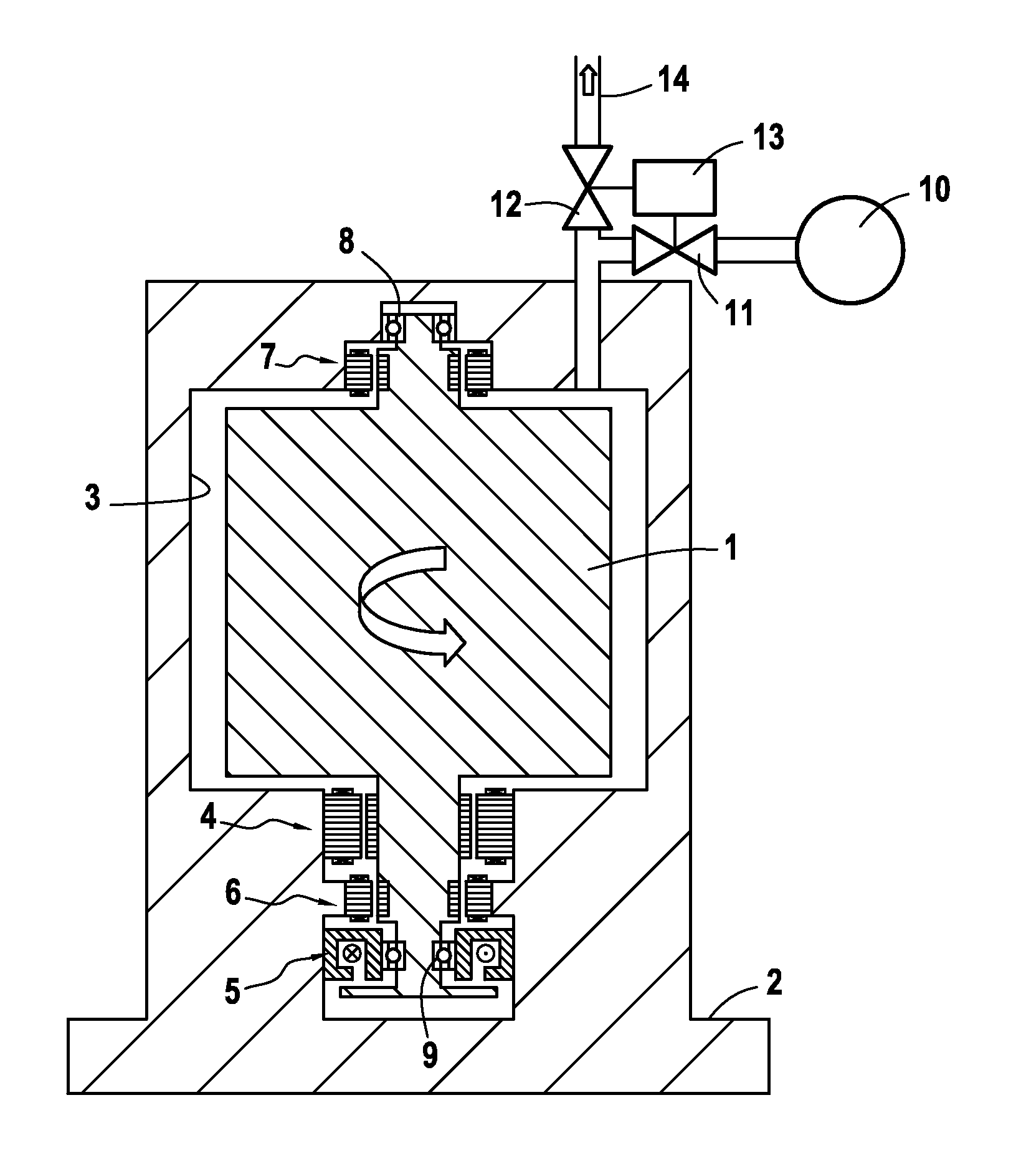
High speed flywheel on magnetic bearings
a magnetic bearing and high-speed technology, applied in the direction of mechanical energy handling, engine components, mechanical apparatus, etc., can solve the problems of large technical effort, high cost, and inability to safely backup bearings, and achieve the effect of selectively creating a braking effect on the rotor
- Summary
- Abstract
- Description
- Claims
- Application Information
AI Technical Summary
Benefits of technology
Problems solved by technology
Method used
Image

Examples
example 1 (
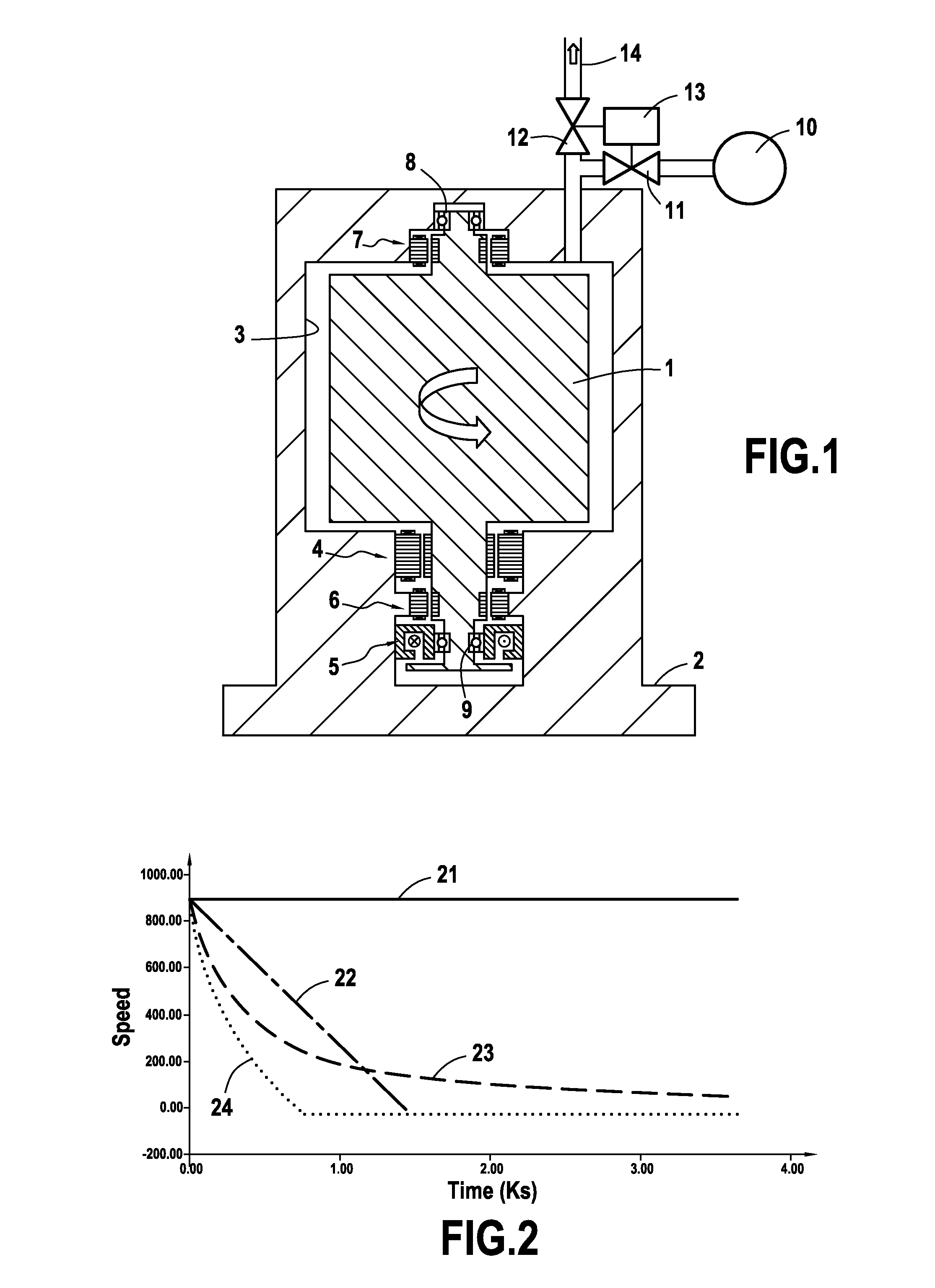
[0044curve 21) corresponds to a spin down in high vacuum with no assistance by the inbuilt generator system (which constitutes the worst case scenario). In such a case, the components 10 to 13 of the present invention are not used.
[0045]Example 2 (curve 22) corresponds to a spin down in high vacuum and with an assistance by the inbuilt generator system. In such a case, the components 10 to 13 of the present invention are not used.
[0046]Example 3 (curve 23) corresponds to a spin down with released nitrogen using the components 10 to 13 of the present invention and with no assistance by the inbuilt generator system (which constitutes the worst case scenario).
example 4 (
[0047curve 24) corresponds to a spin down with released nitrogen using the components 10 to 13 of the present invention and in addition with an assistance by the inbuilt generator system.
[0048]It may be easily seen that in example 1 the spin down process is excessively long and even in example 2 the spin down process cannot be achieved in a few minutes. By contrast examples 3 and 4 where the invention is put into practice enable a very fast spin down operation even in the worst case scenario of curve 23.
[0049]It may be noted that the spin down rate (−df / dt) by gas friction is not constant. In the upper speed range it is very fast and in the lower speed range it is quite low. In the sketched example, the speed reaches 20% of the nominal speed in about 25 minutes. At 20% of the nominal speed 96% of the kinetic energy has already been transferred. A rotation in the backup bearings with speed below 20% of the nominal speed is less time critical. However, if necessary it is possible to i...
PUM
 Abstract
Description
Claims
Application Information