

Imaging lens
a technology of imaging lens and lens body, applied in the field of imaging lens, can solve the problems of difficult to realize imaging lens, inability to meet the needs of compactness and low-profileness, and difficult to correct aberrations in peripheral areas, so as to achieve the effect of reducing production cost and facilitating manufacturing process
- Summary
- Abstract
- Description
- Claims
- Application Information
AI Technical Summary
Benefits of technology
Problems solved by technology
Method used
Image

Examples
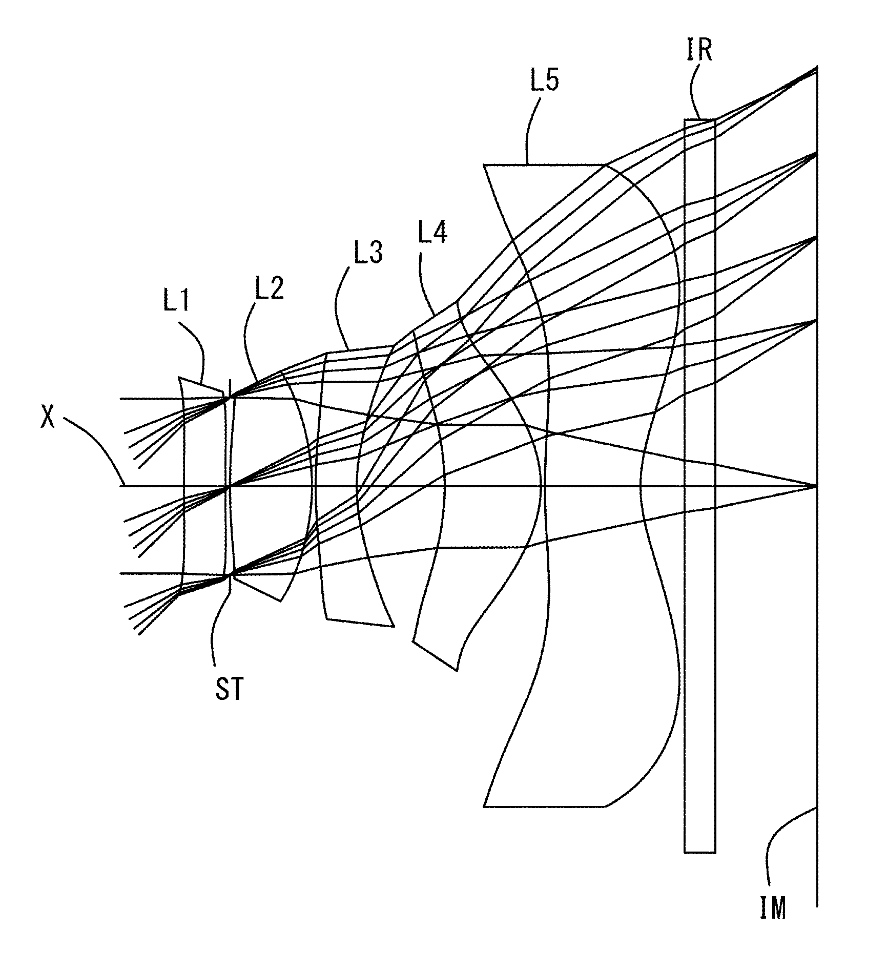
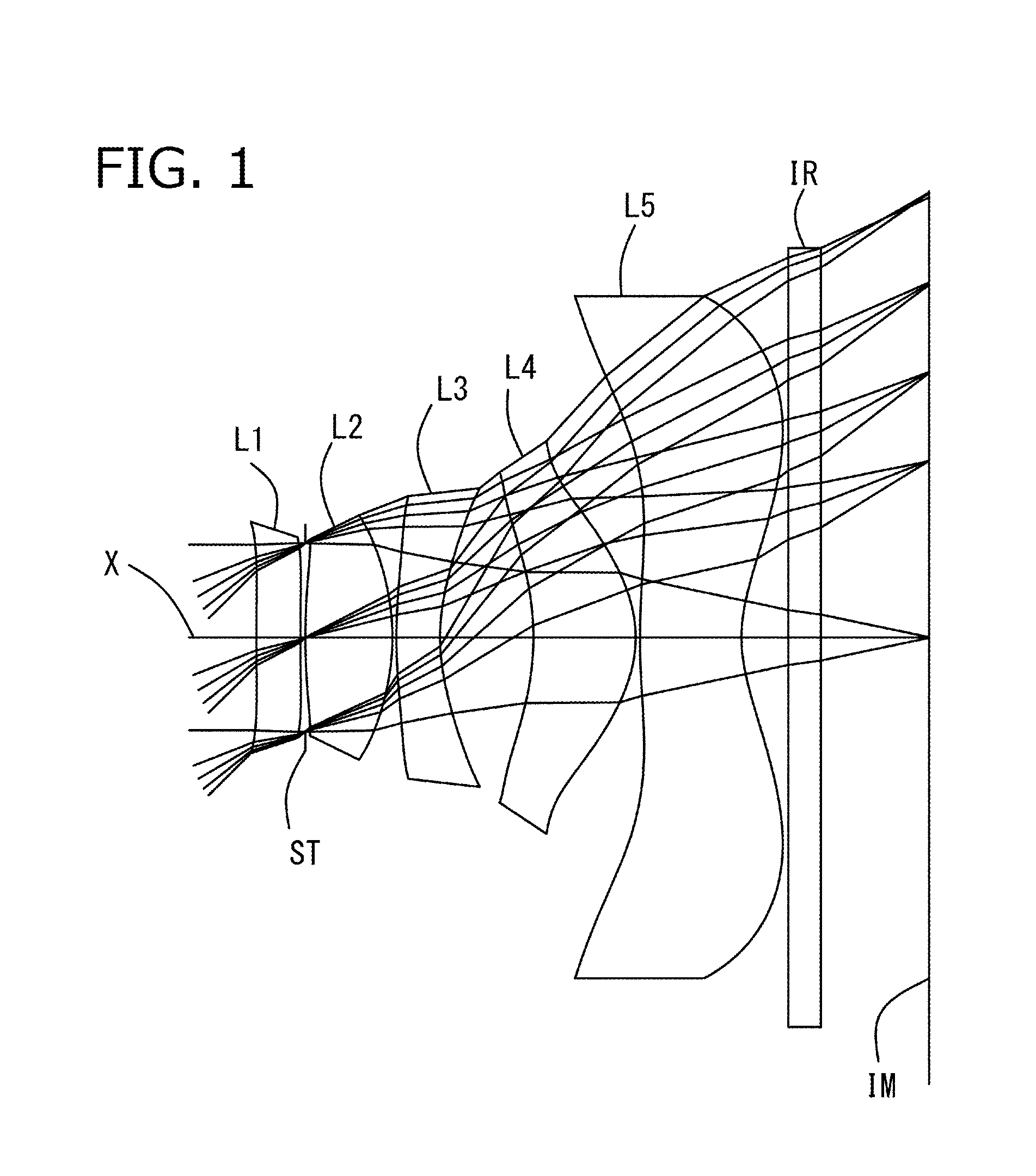
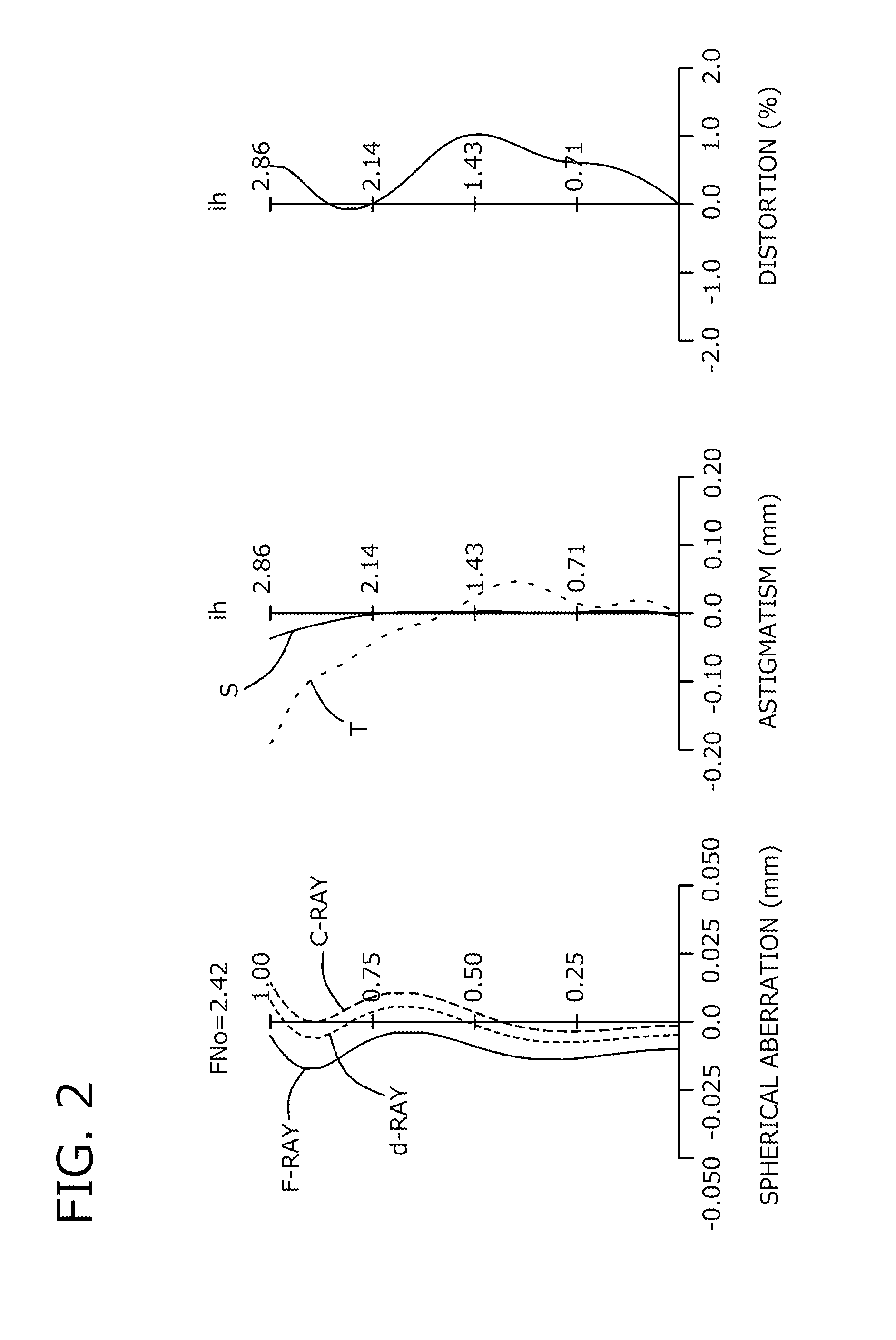
example 1
[0095]The basic lens data of Example 1 is shown below in Table 1.
TABLE 1Numerical Example 1 in mmf = 2.865Fno = 2.42ω(°) = 44.70ih = 2.855Surface DataSurfaceCurvatureSurfaceRefractiveAbbeNo. iRadius rDistance dIndex NdNumber νd(Object Surface)InfinityInfinity 1*15.8690.2821.534656.16 2*17.1160.031 3 (Stop)Infinity0.000 4* 4.4700.5591.543855.57 5*−1.3930.025 6* 3.3250.2801.635523.91 7* 1.2580.599 8*−1.6890.6561.543855.57 9*−0.7850.02810* 4.4570.6511.534656.1611* 0.9560.30012Infinity0.2101.516864.2013Infinity0.693Image PlaneInfinityConstituent Lens DataStartFocalLensSurfaceLength12377.595242.02136−3.360482.146510−2.435Aspheric Surface Data1st2nd4th5th6thSurfaceSurfaceSurfaceSurfaceSurfacek0.000E+002.893E+020.000E+00−1.165E+01 0.000E+00A4−9.322E−02 −1.589E−02 1.155E−01−2.012E−01 −1.418E−01A6−4.164E−01 −4.997E−01 −6.383E−01 6.691E−02−8.522E−02A81.321E+002.717E−015.391E−01−9.255E−03 3.113E−01A10−2.127E+00 −1.646E−01 −6.684E−01 −1.293E−01 −1.145E−01A121.121E+000.000E+000.000E+000.000E+0...
example 2
[0099]The basic lens data of Example 2 is shown below in Table 2.
TABLE 2Numerical Example 2 in mmf = 2.863Fno = 2.43ω(°) = 44.75ih = 2.855Surface DataSurfaceCurvatureSurfaceRefractiveAbbeNo. iRadius rDistance dIndex NdNumber νd(Object Surface)InfinityInfinity 1*13.470 0.2951.534656.16 2*−13.776 0.041 3 (Stop)Infinity0.000 4*9.6770.5441.543855.57 5*−1.537 0.025 6*3.5340.2801.635523.91 7*1.3650.577 8*−1.872 0.7001.543855.57 9*−0.732 0.02810*5.1000.5861.534656.1611*0.8430.30012Infinity0.2101.516864.2013Infinity0.717Image PlaneInfinityConstituent Lens DataStartFocalLensSurfaceLength1212.777242.48136−3.685481.817510−1.984Aspheric Surface Data1st2nd4th5th6thSurfaceSurfaceSurfaceSurfaceSurfacek0.000E+000.000E+000.000E+00−1.259E+01 0.000E+00A4−5.866E−02 1.212E−011.809E−01−2.533E−01 −1.396E−01A6−3.298E−01 −3.355E−01 −5.561E−01 1.228E−01−3.622E−02A81.238E+006.296E−019.067E−015.358E−03 2.276E−01A10−2.039E+00 −8.482E−01 −1.182E+00 −1.449E−01 −6.296E−02A121.123E+000.000E+000.000E+000.000E+00−1....
example 3
[0103]The basic lens data of Example 3 is shown below in Table 3.
TABLE 3Numerical Example 3 in mmf = 2.865Fno = 2.43ω(°) = 44.78ih = 2.855Surface DataSurfaceCurvatureSurfaceRefractiveAbbeNo. iRadius rDistance dIndex NdNumber νd(Object Surface)InfinityInfinity 1*8.9060.2951.534656.16 2*8.2620.077 3 (Stop)Infinity0.072 4*3.4220.6051.543855.57 5*−1.625 0.025 6*4.5490.2801.635523.91 7*1.4230.552 8*−1.880 0.7191.543855.57 9*−0.785 0.03710*6.7330.7581.534656.1611*1.0310.30012Infinity0.2101.516864.2013Infinity0.676Image PlaneInfinityConstituent Lens DataStartFocalLensSurfaceLength12−253.965242.11536−3.374482.011510−2.389Aspheric Surface Data1st2nd4th5th6thSurfaceSurfaceSurfaceSurfaceSurfacek0.000E+00−1.777E+010.000E+00−2.035E+01 0.000E+00A4−1.025E−02 −3.741E−029.968E−02−1.254E−01 −1.744E−01A6−6.245E−01 −4.603E−01−5.622E−01 2.502E−02−9.530E−02A81.530E+00−4.431E−025.695E−014.598E−02 3.823E−01A10−2.242E+00 2.925E−01−9.124E−01 −2.218E−01 −1.869E−01A121.121E+00 0.000E+000.000E+000.000E+00−1.6...
PUM
 Abstract
Description
Claims
Application Information