Chain guide

a chain and guide technology, applied in the direction of belts/chains/gearrings, mechanical instruments, belts/chains/gears, etc., can solve the problems of increasing machining costs, requiring large machining machines, and requiring certain degrees of rigidity and durability of guides, so as to prevent the fixing from being loosened, reduce maintenance work load, and prevent vibration and noise during use.

Inactive Publication Date: 2014-07-31
TSUBAKIMOTO CHAIN CO
View PDF55 Cites 7 Cited by
  • Summary
  • Abstract
  • Description
  • Claims
  • Application Information

AI Technical Summary

Benefits of technology

[0030]Further, since concentrated stress is not applied to all the attaching sections, it is possible to surely prevent the fixing from being loosened, prevent an increase in vibration and noise during use, and reduce a maintenance work load.
[0031]With a configuration described in claim 6, the base member is integrated with the guide shoe by, for example, molding during manufacturing of the guide shoe. Therefore, it is possible to omit an assembly process and reduce manufacturing costs.
[0032]With a configuration described in claim 7, the base member is configured to be detachably attachable to the guide shoe. Therefore, it is possible to individually design the base member and the guide shoe and it is possible to cope with different specifications by combining the base member and the guide shoe as appropriate. As a result, versatility is improved.
[0033]With a configuration described in claim 8, the ba

Problems solved by technology

However, the chain guide requires certain degrees of strength, rigidity, and durability in order to stably guide a chain against the tension and the vibration of the cha

Method used


Image

  • Chain guide
  • Chain guide
  • Chain guide

Examples


first embodiment

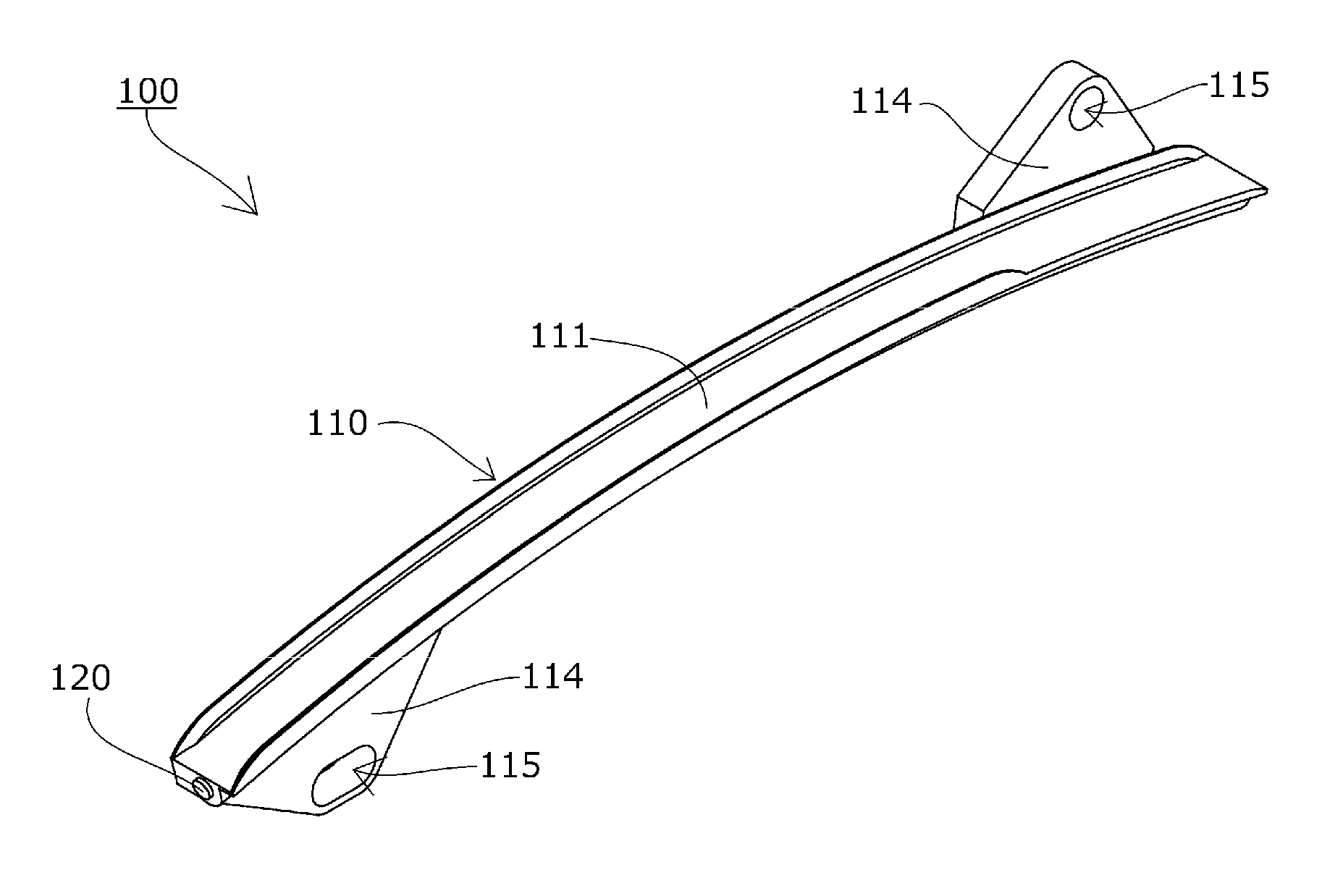
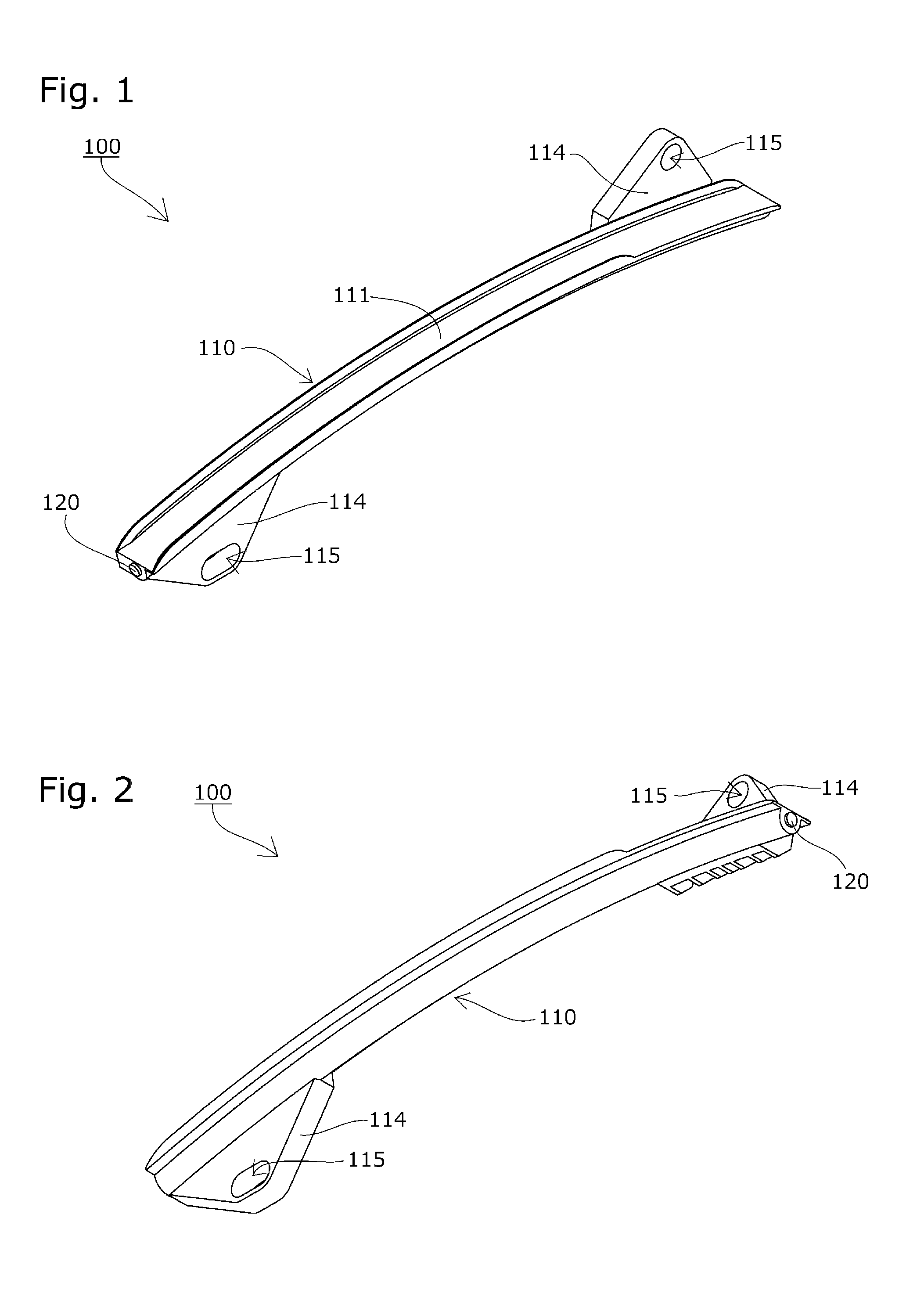
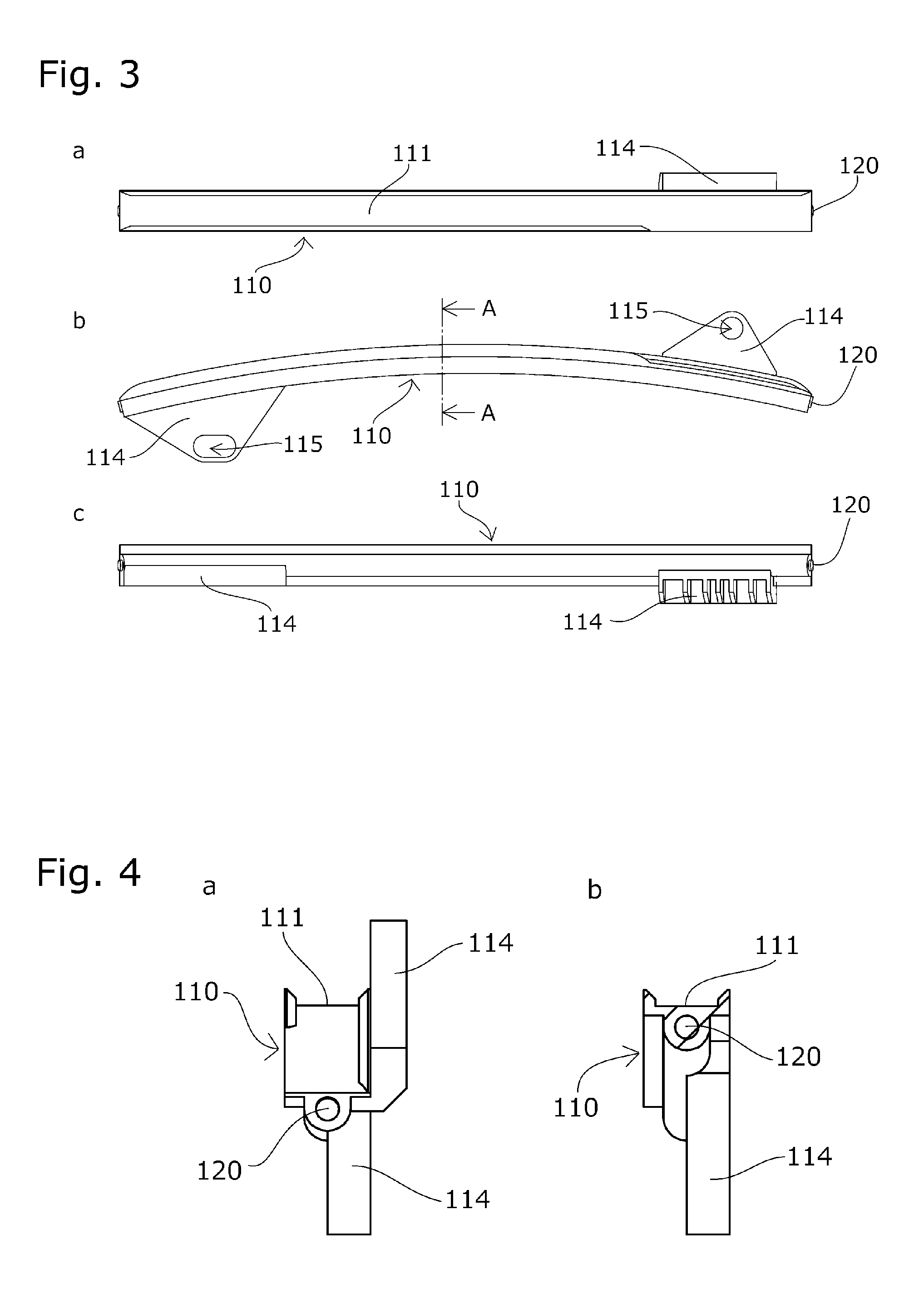
[0063]A chain guide 100 (a fixed guide) according to a first embodiment of the present invention is explained based on the drawings.

[0064]The chain guide 100 is applied to the publicly-known timing system explained above. As shown in FIG. 1 to FIGS. 4A and 4B, the chain guide 100 includes a guide shoe 110 configured to slide and guide a traveling chain and a base member 120 configured to reinforce the guide shoe 110 along a chain traveling direction and improve strength, rigidity, and durability.

[0065]The base member 120 is formed of a bar of metal extending in the chain traveling direction. The base member 120 is formed by, for example, drawing a steel material and cutting the steel material at appropriate length.

[0066]The base member 120 is given a predetermined bending shape along the chain traveling direction.

[0067]The guide shoe 110 includes a traveling guide section 111 extending in the chain traveling direction. The guide shoe 110 is formed of a synthetic resin material and i...

second embodiment

[0081]A chain guide 200 (a fixed guide) according to a second embodiment of the present invention is explained based on the drawings.

[0082]The chain guide 200 is applied to the publicly-known timing system explained above. As shown in FIG. 7 to FIGS. 10A and 10B, the chain guide 200 includes a guide shoe 210 configured to slide and guide a traveling chain and a base member 220 configured to reinforce the guide shoe 210 along a chain traveling direction and improve strength, rigidity, and durability.

[0083]The guide shoe 210 includes a traveling guide section 211 extending in the chain traveling direction. The guide shoe 210 is formed of a synthetic resin material and integrally molded by, for example, injection molding in a state in which an intermediate portion of the base member 220 is inserted into the guide shoe 210.

[0084]The base member 220 is formed of a bar of metal extending in the chain traveling direction. The base member 220 is formed by, for example, drawing a steel mater...

third embodiment

[0104]A chain guide 300 (a swinging guide) according to a third embodiment of the present invention is explained based on the drawings.

[0105]The chain guide 300 is applied to the publicly-known timing system explained above. As shown in FIG. 15 to FIGS. 18A and 18B, the chain guide 300 includes a guide shoe 310 configured to swing around an attachment hole 315 and slide and guide a traveling chain and a base member 320 configured to reinforce the guide shoe 310 along a chain traveling direction and improve strength, rigidity, and durability.

[0106]The base member 320 is formed of a bar of metal extending in the chain traveling direction. The base member 320 is formed by, for example, drawing a steel material and cutting the steel material at appropriate length.

[0107]The base member 320 is given a predetermined bending shape along the chain traveling direction.

[0108]The guide shoe 310 is formed of a synthetic resin material. The guide shoe 310 includes a traveling guide section 311 ex...


PUM


Abstract

By employing a simple configuration, a space required for engine room can be minimized while securing enough strength, rigidity, and durability, and a reduction in a material waste, manufacturing processes, and manufacturing cost can be accomplished while occurrence of a crack or breakage during use is prevented. A chain guide includes a guide shoe, a base member configured to reinforce the guide shoe, and attaching sections. The base member is formed by a bar made of a metal material.

Description

BACKGROUND OF THE INVENTION[0001]1. Field of the Invention[0002]The present invention relates to a chain guide including a guide shoe configured to slide and guide a traveling chain, a base member configured to reinforce the guide shoe along a chain traveling direction, and at least one attaching section.[0003]2. Description of the Related Art[0004]In order to stabilize a chain traveling between sprockets and properly retain tension, a chain guide including a guide shoe configured to slide and guide the traveling chain has been used in common.[0005]For example, a timing system for an engine is publicly known that drives a driving chain CH such as a roller chain endlessly wound between sprockets S1 and S2 respectively provided in a crank shaft and a cam shaft in an engine room as shown in FIG. 23. The timing chain CH is endlessly wound between a driving sprocket S1 attached to the crank shaft and a pair of driven sprockets S2 attached to the cam shaft in the engine room E. The timing...

Claims


Application Information

Patent Timeline
IPC IPC(8): F16H7/18
CPCF16H7/18F16H2007/0872
Inventor KONNO, MASAHIKOMORI, KAORIISHIKAWA, YUICHIROTAKAGI, YUDAI
Owner TSUBAKIMOTO CHAIN CO
Why Eureka
Try Eureka