Cooling assembly and dehumidification method

a technology of cooling assembly and dehumidification method, which is applied in the direction of defrosting, heating types, domestic cooling apparatus, etc., can solve the problems of increasing climate problems, and affecting the cooling effect of electronic components

Inactive Publication Date: 2014-08-07
ABB OY
View PDF18 Cites 14 Cited by
  • Summary
  • Abstract
  • Description
  • Claims
  • Application Information

AI Technical Summary

Benefits of technology

[0006]An exemplary embodiment of the present disclosure provides a cooling assembly which includes a device chamber containing a device chamber cooling medium, heat exchanger means comprising at least one cooling surface in contact with the device chamber cooling medium, control means for controlling the heat exchanger means, humidity sensor means for detecting a humidity level in the device chamber, and a receptacle. The control means is configured to perform a dehumidification operation as a response to the detected humidity level exceeding a predetermined threshold value in the device chamber. The dehumidification operation comprises lowering a temperature of the at least one cooling surface to condensate water from the device chamber cooling medium on the at least one cooling surface. The receptacle is configured to receive water dripping from the at least one cooling surface.

Problems solved by technology

Humidity is harmful to many electronic components.
Humidity is an issue, for example, in solar power plants and wind power plants.
Challenging environments such as tropical or arctic climates increase problems caused by humidity.
Dehumidification by repeated drying cycles discharging heated humid air and replacing the discharged air with colder ambient air is a relatively slow process requiring plenty of energy.
Water absorbing materials are expensive and their useful life is limited.

Method used


Image

  • Cooling assembly and dehumidification method
  • Cooling assembly and dehumidification method

Examples


Embodiment Construction

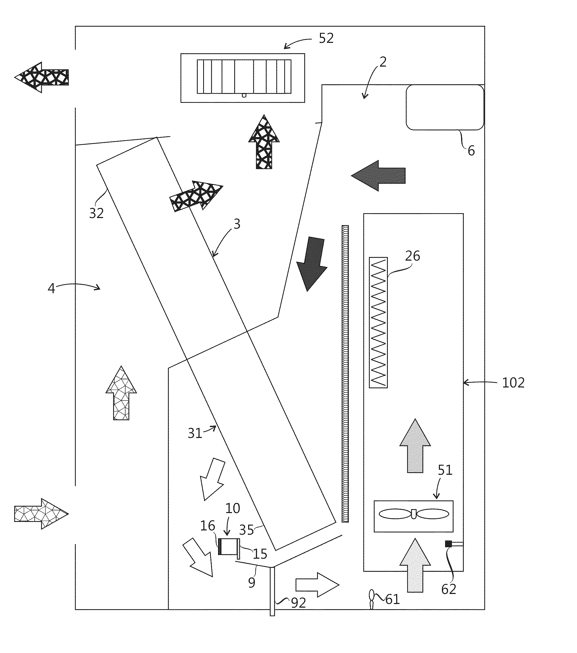
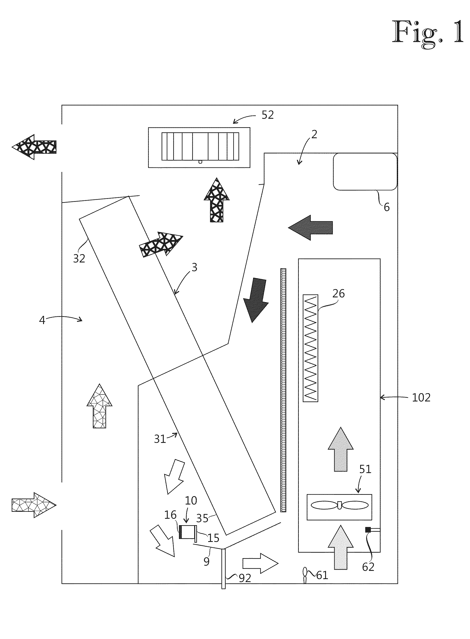
[0010]Exemplary embodiments of the present disclosure provide a method and an apparatus for implementing the method so as to alleviate the above disadvantages. Exemplary embodiments of the present disclosure provide a dehumidification method and a cooling assembly as described herein.

[0011]Exemplary embodiments of the present disclosure are based on the idea of condensing water from a device chamber cooling medium by cooling thereof at a safe place at a distance from electronic components that could be damaged by humidity. The condensed water may be discharged from a device chamber containing the electronic components or stored inside the device chamber in a harmless place where the water does not endanger the electronic components.

[0012]An advantage of the method and assembly of the present disclosure is that the cooling medium in a device chamber can be dried relatively fast without need to discharge heated cooling medium from the device chamber.

[0013]In the following, exemplary e...


PUM


Abstract

A cooling assembly includes a device chamber containing a device chamber cooling medium, a heat exchanger including at least one cooling surface in contact with the device chamber cooling medium, a control unit configured to control the heat exchanger, a humidity sensor configured to detect a humidity level in the device chamber, and a receptacle. The control unit is configured to perform a dehumidification operation as a response to the humidity level exceeding a predetermined threshold value in the device chamber. The dehumidification operation includes lowering a temperature of the at least one cooling surface in order to condensate water from the device chamber cooling medium on the at least one cooling surface. The receptacle is configured to receive water dripping from the at least one cooling surface.

Description

RELATED APPLICATION[0001]This application claims priority under 35 U.S.C. §119 to European Patent Application No. 13153815.9 filed in Europe on Feb. 4, 2013, the entire content of which is hereby incorporated by reference in its entirety.FIELD[0002]The present disclosure relates to a cooling assembly and to a dehumidification method.BACKGROUND INFORMATION[0003]Humidity is harmful to many electronic components. Humidity is an issue, for example, in solar power plants and wind power plants. Challenging environments such as tropical or arctic climates increase problems caused by humidity.[0004]In a known method, air inside a device chamber is heated after which the heated moist air is discharged from the device chamber, and the cycle is repeated until air inside the device chamber is warm and dry. It is also known to use water absorbing materials such as silica gel to remove humidity from a device chamber.[0005]Dehumidification by repeated drying cycles discharging heated humid air and...

Claims


Application Information

Patent Timeline
Patent Type & Authority Applications(United States)
IPC IPC(8): F25D29/00
CPCF25D29/00F24F3/14F25D21/14F24F2003/1446F24F2013/227F24F13/222H05K7/20609H05K7/207
Inventor KOIVULUOMA, TIMOMANNINEN, JORMA
Owner ABB OY
Why Eureka
Try Eureka