
Air-cooling cylinder head of gasoline engine and gasoline engine having the same

Inactive Publication Date: 2014-08-07
LONCIN MOTOR
View PDF2 Cites 2 Cited by
  • Summary
  • Abstract
  • Description
  • Claims
  • Application Information

AI Technical Summary

Benefits of technology

The invention is an air-cooling cylinder head for a gasoline engine that improves cooling efficiency, ensures the physical performance of the cylinder head, and reduces the temperature of the cylinder. This allows the gasoline engine to operate stably for a longer time. Additionally, the invention can effectively decrease the hydrocarbon in the tail gas and prevent piston sticking and scuffing of cylinder due to temperature rise.

Problems solved by technology

The heat has to be inevitably transferred through the heat conduction of the cylinder body and the cylinder head to the outer surface and then transferred to the outside through other cooling manners, and quick cooling is required to maintain the normal working of the combustion chamber surface; otherwise, limitless rise of the temperature of the combustion chamber wall surface may be caused, finally the tail gas emission may be influenced and the use of the cylinder head may be influenced, even piston sticking and scuffing of cylinder may be caused.
However, when the gasoline engine operates for a long time, as the heat conduction performance and the convection area of the cooling fins are limited, cooling is insufficient; the accumulation of heat may influence the physical performance of the cylinder head, further influence the operating performance of the gasoline engine, even cause accidents and make the gasoline engine scrapped.

Method used


Image

  • Air-cooling cylinder head of gasoline engine and gasoline engine having the same
  • Air-cooling cylinder head of gasoline engine and gasoline engine having the same
  • Air-cooling cylinder head of gasoline engine and gasoline engine having the same

Examples


Embodiment Construction

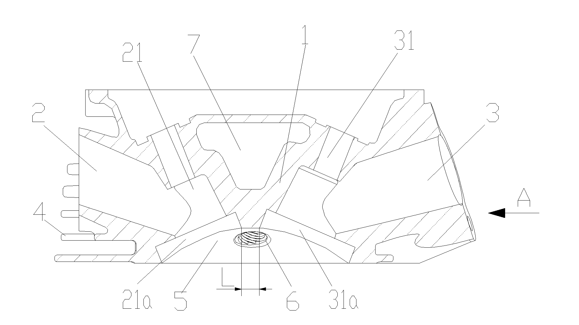
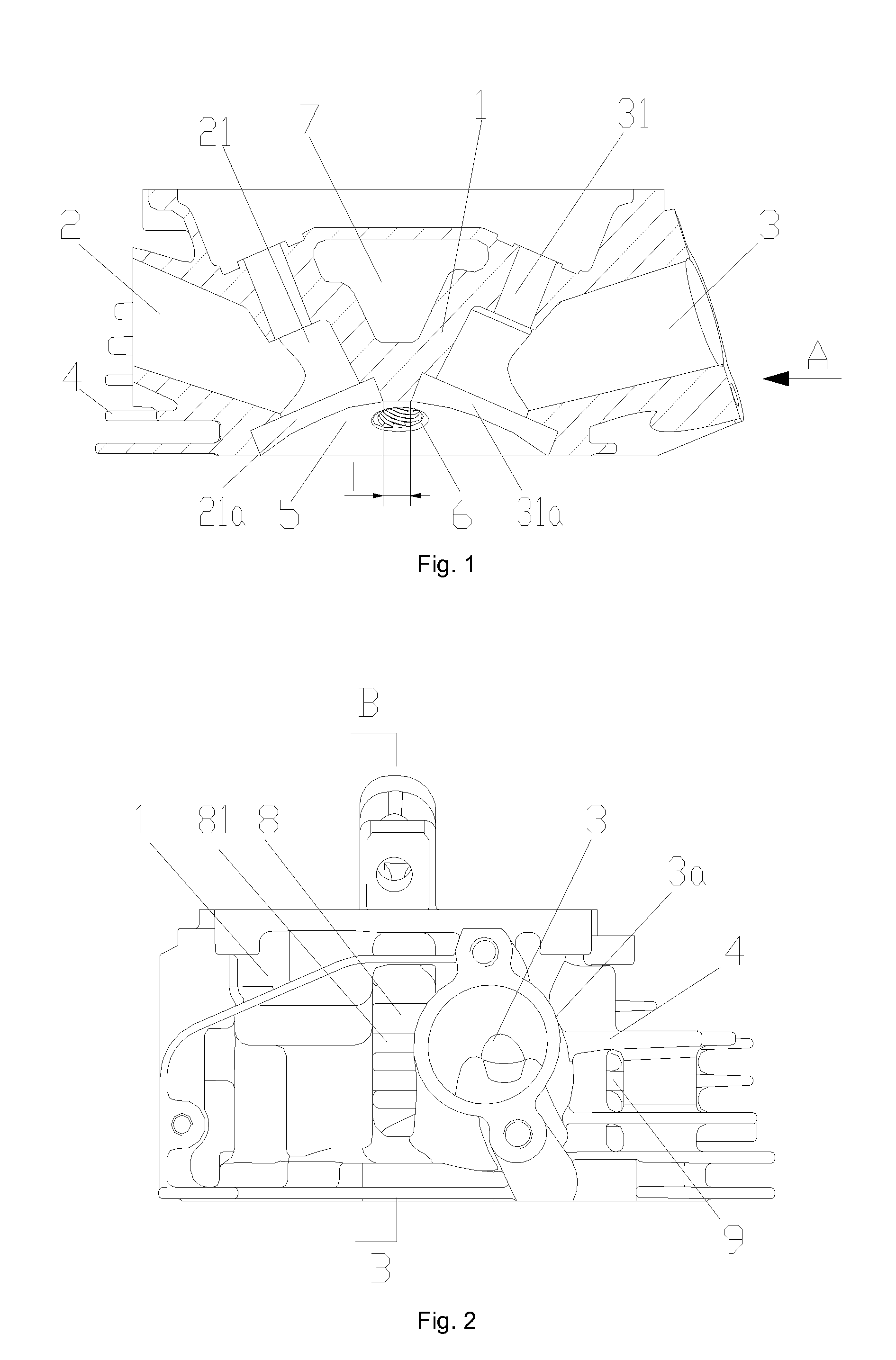
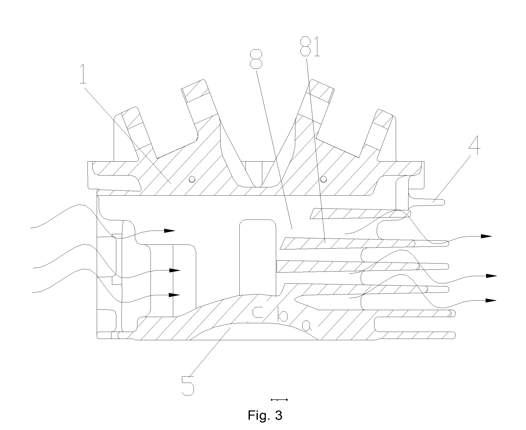
[0028]FIG. 1 shows a structure view of the invention, FIG. 2 shows a view of FIG. 1 along the direction A, FIG. 3 shows the view of FIG. 2 along the direction B-B, FIG. 4 shows a front view of the spark plug air-cooling passage, FIG. 5 shows a mounting structure view of rocker arms, and FIG. 6 shows a sectional view of the coordination between rocker arm shafts and rocker arm bases. As shown in the drawings: the air-cooling cylinder head of a gasoline engine in the embodiment comprises a cylinder head main body 1, and an intake passage 3, an exhaust passage 2 and a spark plug mounting hole 6 arranged in the cylinder head main body 1, a plurality of cooling fins 4 is arranged on the outer surface of the cylinder head main body 1, a combustion chamber surface 5 is formed on the inner side of the cylinder head main body 1, a longitudinally through air-cooling passage I 8 is arranged on the same side of the cylinder head main body 1 as the intake passage 3 and the exhaust passage 2, a t...


PUM


Abstract

The invention discloses an air-cooling cylinder head of a gasoline engine and a gasoline engine. The air-cooling cylinder head of a gasoline engine comprises a cylinder head main body (1), and an intake passage (3), an exhaust passage (2) and a spark plug mounting hole (6) arranged in the cylinder head main body (1), a plurality of cooling fins (4) is arranged on the outer surface of the cylinder head main body (1), a combustion chamber surface (5) is formed on the inner side of the cylinder head main body (1), a longitudinally through air-cooling passage I (8) is arranged on the same side of the cylinder head main body (1) as the intake passage (3) and the exhaust passage (2), a transversally through air-cooling passage II (7) is arranged between the intake passage (3) and the exhaust passage (2), and both the longitudinally through air-cooling passage I (8) and the transversally through air-cooling passage II (7) are kept away from function holes on the cylinder head main body (1). In the technical solution of the invention, cooling air flows through the outer surface of the combustion chamber wall from different directions to sufficiently decrease the temperature of the combustion chamber, so that the cylinder head has excellent cooling efficiency, and the power of the gasoline engine is increased.

Description

TECHNICAL FIELD OF THE INVENTION[0001]The invention relates to the field of power machinery, in particular to an air-cooling cylinder head of a gasoline engine and a gasoline engine having the same.BACKGROUND OF THE INVENTION[0002]General-purpose gasoline engines are reciprocating piston gasoline engines with broad applications, except applications in vehicle and aeroplane. Generally, those with a power within 20 kW are called as small general-purpose gasoline engines; and they have high generality and advantages of small volume, small mass, simple and convenient use and operation, and low price. As one of power sources, the general-purpose gasoline engine is used for driving general-purpose machinery, including agriculture and forestry plant protection machinery, garden machinery, power generation sets and construction machinery and the like. As a kind of power machinery using gasoline as fuel, the gasoline engine consists of a cylinder, a crank and connecting rod mechanism, a dist...

Claims


Application Information

Patent Timeline
IPC IPC(8): F01P1/02
CPCF01P1/02F01P1/10F02F1/06
Inventor LIU, BINGXIE, YUMINGCHEN, HONGBO
Owner LONCIN MOTOR
Learn More