Hydrogen dispenser test apparatus and method

a technology of hydrogen dispensers and test apparatuses, which is applied in the direction of liquid handling, container discharging methods, packaging goods, etc., can solve the problem that none of the aforementioned references discloses apparatus or methods for testing the performance of hydrogen dispensers

Inactive Publication Date: 2014-08-07
CANADIAN STANDARDS ASSOC GRP
View PDF0 Cites 33 Cited by
  • Summary
  • Abstract
  • Description
  • Claims
  • Application Information

AI Technical Summary

Benefits of technology

[0010]According to an aspect of the disclosure, an apparatus for testing a hydrogen dispenser includes a first tank, a supply channel fluidly coupled to the first tank, the supply channel configured to be fluidly coupled to the hydrogen dispenser, a backpressure system fluidly coupled to the first tank, and a controller operatively coupled to the backpressure system. The controller is configured to receive a target fill profile, and control the backpressure system to effect a fill profile according to the target fill profile.
[0011]Another aspect of the disclosure provides a method for testing a hydrogen dispenser using a test apparatus. The test apparatus includes a first tank, a supply channel fluidly coupled to the first tank, the supply channel configured to be coupled to the hydrogen dispenser, a backpressure system fluidly coupled to the first tank, and a controller operatively coupled to the backpressure system. The method includes receiving a target fill profile via the controller, dispensing hydrogen from the hydrogen dispenser to the test apparatus through the first valve, and controlling the backpressure system via the controller to effect a fill profile according to the target fill profile.
[0012]Another aspect of the disclosure provides an article of manufacture. The article of manufacture includes a machine-readable non-volatile medium having instructions encoded thereon for enabling a processor to perform the operations of dispensing hydrogen from a hydrogen dispenser to a first tank through a supply channel disposed between the hydrogen dispenser and the first tank, receiving a target fill profile, and controlling a backpressure system fluidly coupled to the first tank to effect a fill profile according to the target fill profile.

Problems solved by technology

However, none of the aforementioned references disclose apparatus or methods for testing the performance of hydrogen dispensers.

Method used


Image

  • Hydrogen dispenser test apparatus and method
  • Hydrogen dispenser test apparatus and method
  • Hydrogen dispenser test apparatus and method

Examples


Embodiment Construction

[0043]Various embodiments of the invention will now be described with reference to the drawing figures, in which like reference numerals refer to like parts throughout.

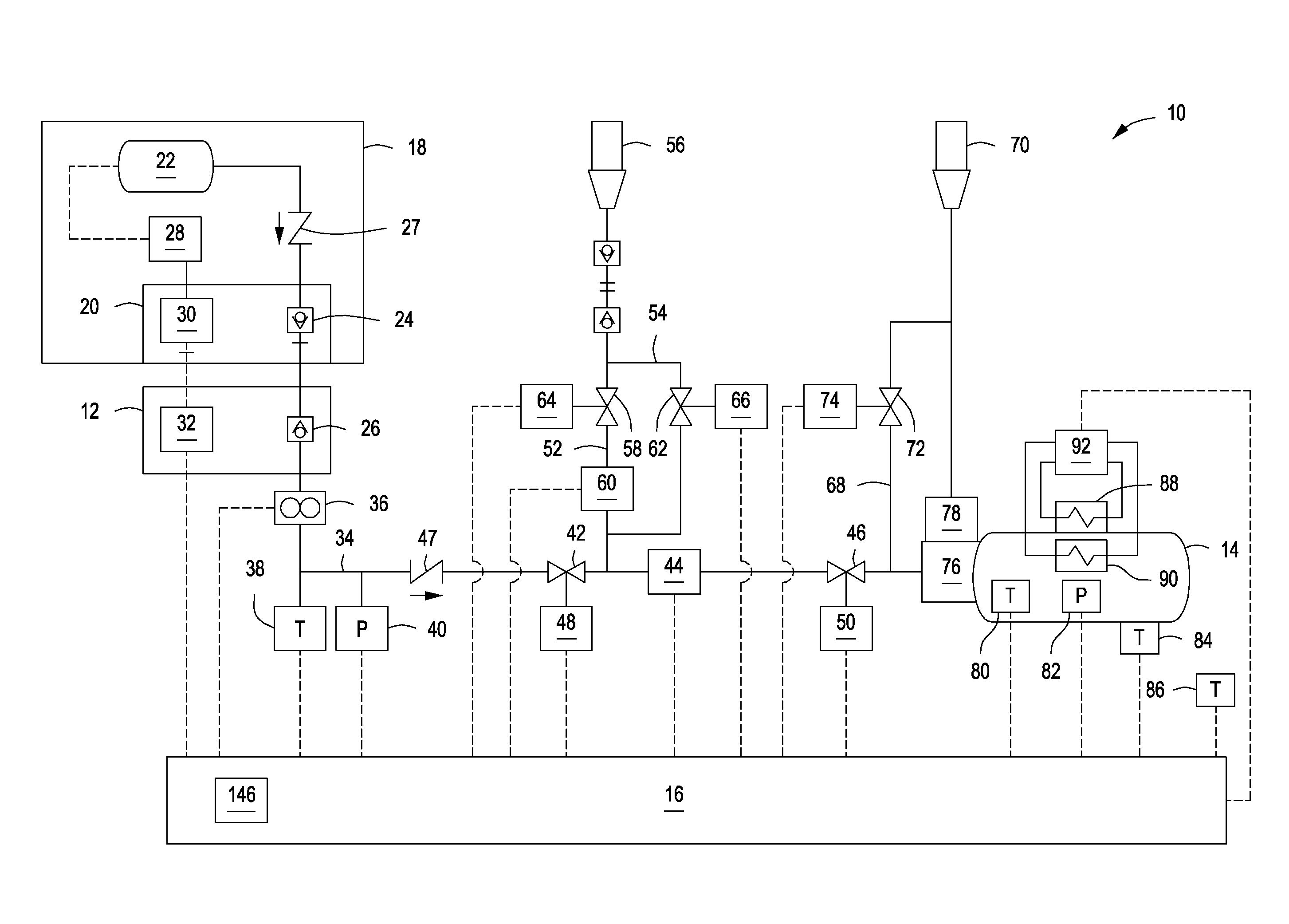
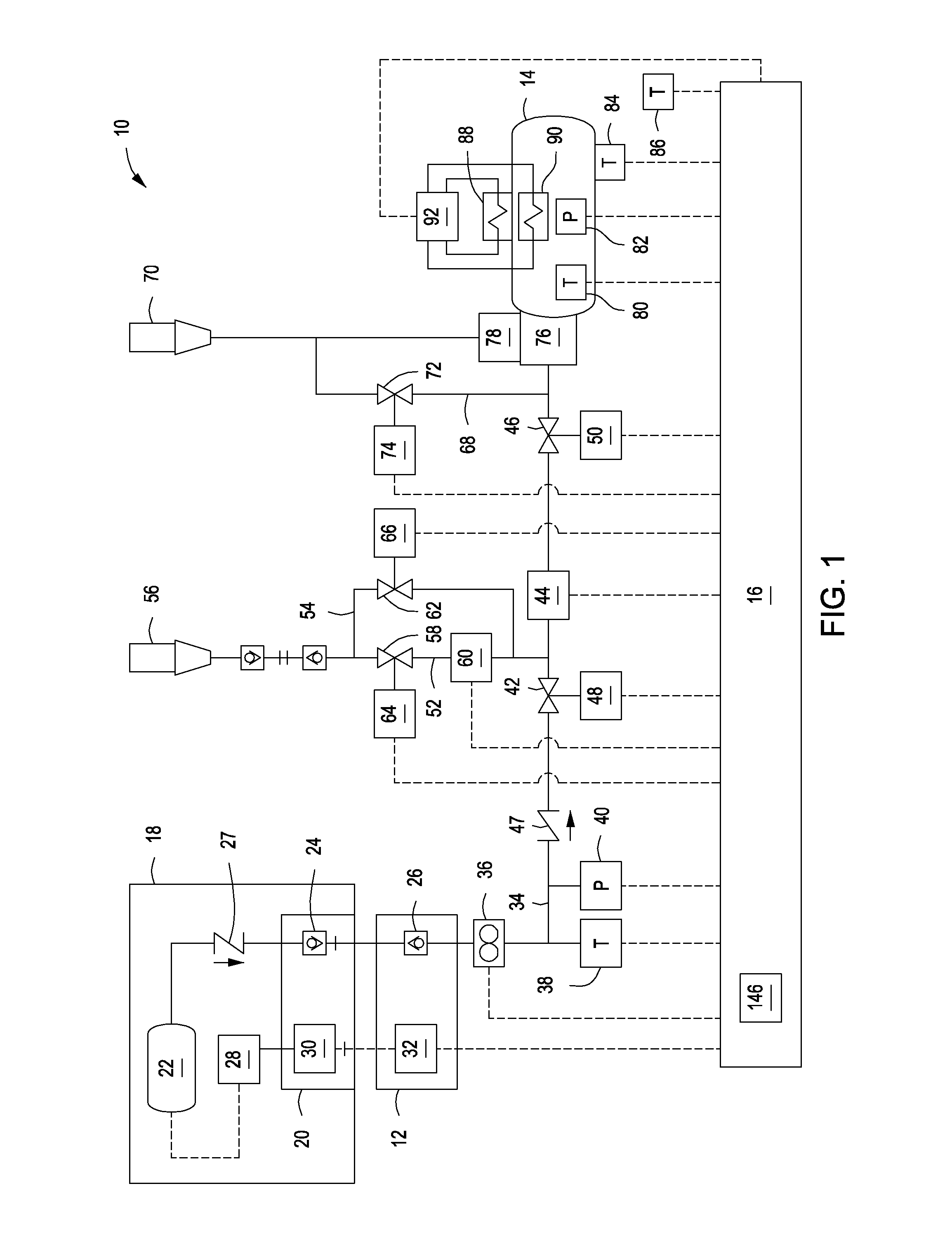
[0044]FIG. 1 illustrates a schematic for a hydrogen dispenser test apparatus 10 (HDTA) according to an embodiment of the invention. The HDTA 10 includes an HDTA receptacle 12 that is in fluid communication with a tank 14 and that is in electrical communication with an HDTA controller 16. The HDTA receptacle 12 is configured to couple the HDTA 10 to a hydrogen dispenser 18 through a dispenser receptacle 20.

[0045]In one embodiment, the hydrogen dispenser 18 includes a pressurized hydrogen storage system 22 in fluid communication with a dispenser fluid coupling 24 within the dispenser receptacle 20. Coupling the dispenser fluid coupling 24 with an HDTA fluid coupling 26 of the HDTA receptacle 12 effects fluid communication between the HDTA 10 and the hydrogen dispenser 18. The hydrogen dispenser 18 may include a check va...


PUM

PropertyMeasurementUnit
pressuresaaaaaaaaaa
diameteraaaaaaaaaa
diameteraaaaaaaaaa

Abstract

An apparatus and a method for testing a hydrogen dispenser is disclosed. The apparatus includes a first tank, a supply channel fluidly coupled to the first tank, the supply channel configured to be fluidly coupled to the hydrogen dispenser, a backpressure system fluidly coupled to the first tank, and a controller operatively coupled to the backpressure system. The controller is configured to receive a target fill profile, and control the backpressure system to effect a fill profile according to the target fill profile.

Description

CROSS-REFERENCE TO RELATED APPLICATIONS[0001]This application claims priority to U.S. Provisional Patent Application No. 61 / 762,091, filed on Feb. 7, 2013, and U.S. Provisional Patent Application No. 61 / 779,345, filed on Mar. 13, 2013, the entire disclosures of which are hereby incorporated by reference.FIELD OF THE INVENTION[0002]The invention relates generally to gaseous fuel distribution systems. More particularly, the invention relates to apparatus and methods for testing hydrogen distribution systems.BACKGROUND OF THE INVENTION[0003]Apparatus and methods for distributing gaseous fuels, including hydrogen, have been proposed. For example U.S. Pat. No. 7,059,364 (hereinafter “the '364 patent”) describes a method and system for fueling hydrogen-fueled vehicles, including internal combustion engine and fuel cell powered vehicles. The algorithm used to control the fill process in the '364 patent determines the hydrogen storage vessel capacity of the vehicle being filled without the ...

Claims


Application Information

Patent Timeline
Patent Type & Authority Applications(United States)
IPC IPC(8): F17C5/00F17C13/02
CPCF17C13/025F17C5/007F17C5/00F17C5/06F17C2201/056F17C2201/058F17C2205/0326F17C2205/0332F17C2205/0341F17C2205/037F17C2221/012F17C2223/0123F17C2223/035F17C2223/036F17C2225/045F17C2227/0304F17C2227/0379F17C2227/0383F17C2227/04F17C2250/032F17C2270/0168F17C2270/0184Y02P90/45Y02E60/32
Inventor LOEWENTHAL, KENNETH A.
Owner CANADIAN STANDARDS ASSOC GRP
Why Eureka
Try Eureka