Power transmission device

a technology of power transmission device and transmission device, which is applied in the direction of wind energy generation, liquid fuel engine components, dynamo-electric brakes/clutches, etc., can solve the problems of limited installation of power transmission device, hardly has a long service life, and noise and vibration, and achieves a wide range of acceleration and deceleration. , the effect of greater allowable torqu

Inactive Publication Date: 2014-08-07
SANYO DENKI CO LTD
View PDF2 Cites 36 Cited by
  • Summary
  • Abstract
  • Description
  • Claims
  • Application Information

AI Technical Summary

Benefits of technology

[0016]Consequently, it is possible to provide a power transmission device which is small and ca

Problems solved by technology

A power transmission device which uses a gear mechanism transmits power while gears directly contact each other, and therefore causes noise and vibration and hardly has a long service life.
Maintenance of a power transmission device which uses a gear mechanism is limited needs to be taken into account, and therefore the place to install the power transmission device is limited and the degree of freedom of design is restricted.
However, according to the magnetic accelerating/decelerating device disclosed in US 2011/0057456, an area in which the magnet of the high speed rotor and the magnet of the low speed rotor oppose to each other needs to be made large

Method used


Image

  • Power transmission device
  • Power transmission device
  • Power transmission device

Examples


first embodiment

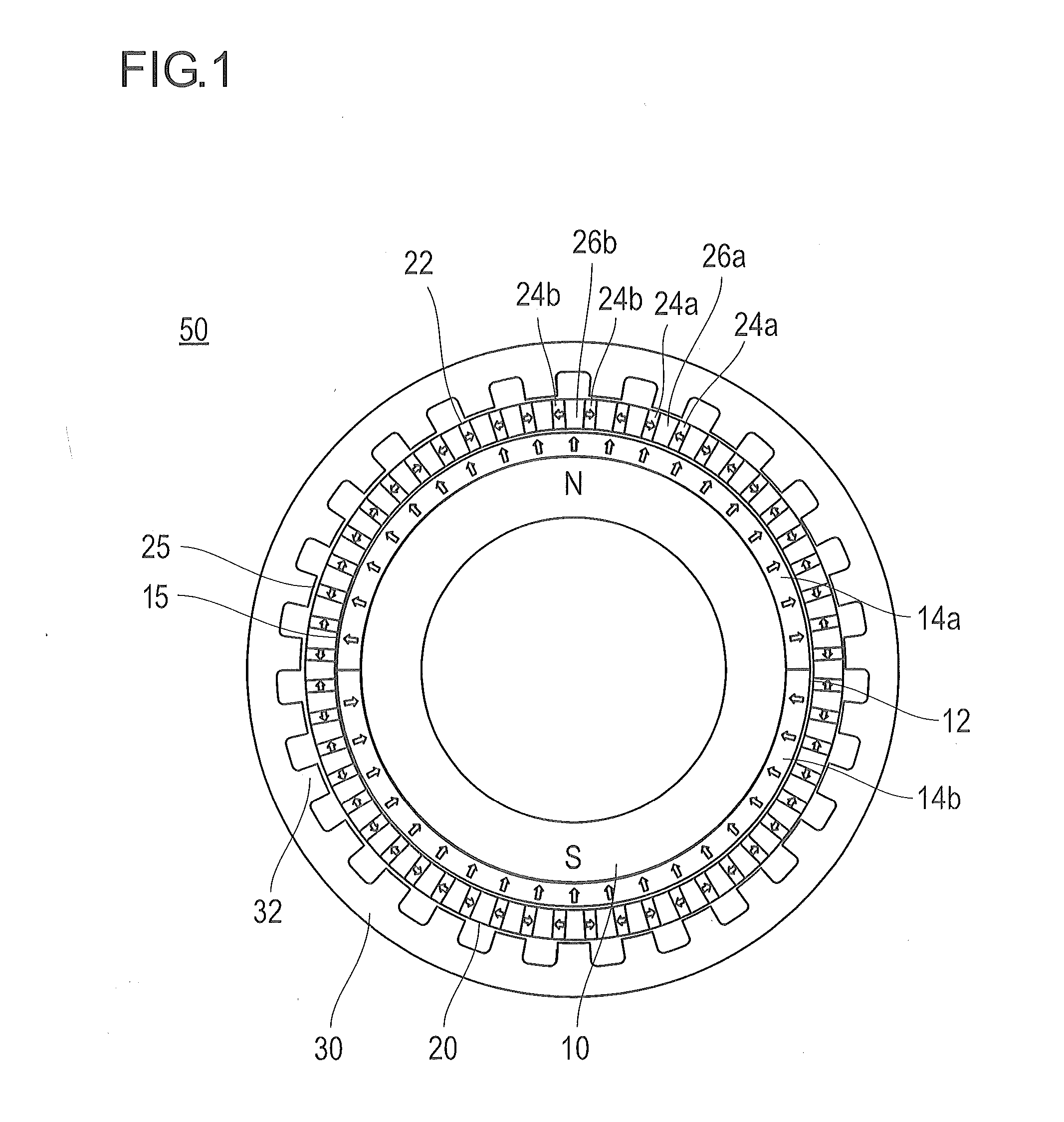
[0053]FIG. 1 is a configuration diagram of a power transmission device according to the first embodiment. FIG. 2 is an explanatory view of closed magnetic fields formed in the power transmission device in FIG. 1. FIG. 3 is an explanatory view of power transmission of the power transmission device. FIGS. 4 to 6 are explanatory views of a mechanism of power transmission of the power transmission device in FIG. 1. Hereinafter, a configuration and an operation of the power transmission device according to the present embodiment will be described.

[0054]

[0055]FIG. 1 is a configuration diagram of the power transmission device according to the present embodiment, and illustrates a cross section obtained by cutting the power transmission device in a direction orthogonal to a rotation axis direction of the power transmission device. In addition, directions of arrows illustrated in FIG. 1 are magnetizing directions of permanent magnets, and arrow directions of the arrows indicate the N pole an...

second embodiment

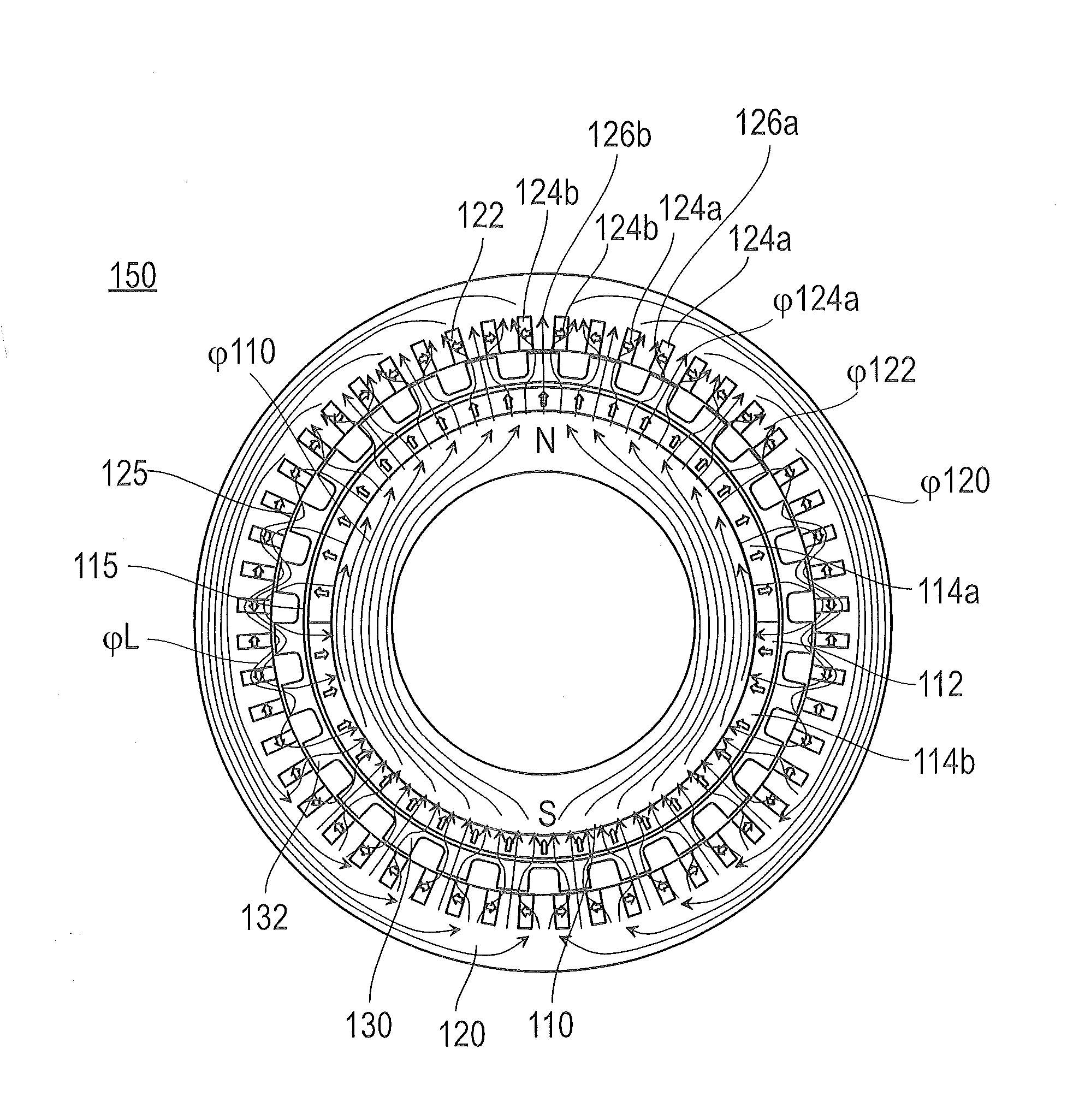
[0133]Next, a power transmission device according to the second embodiment will be described. FIG. 7 is a configuration diagram of the power transmission device according to the second embodiment. FIG. 8 is an explanatory view of closed magnetic fields formed in the power transmission device in FIG. 7.

[0134]As illustrated in FIG. 7, a power transmission device 150 according to the second embodiment differs from a power transmission device 50 according to the first embodiment in switching positions of a low speed magnet rotor and an inductor rotor.

[0135]

[0136]The power transmission device 150 includes a high speed magnet rotor 110, a low speed magnet rotor 120 and an inductor rotor 130. The high speed magnet rotor 110, the low speed magnet rotor 120 and the inductor rotor 130 are concentrically arranged. In the present embodiment, the high speed magnet rotor 110 of the smallest diameter is arranged on an innermost side, and the low speed magnet rotor 120 of the largest diameter is ar...

third embodiment

[0153]Next, a power transmission device according to the third embodiment will be described. FIG. 9 is a configuration diagram of the power transmission device according to the third embodiment.

[0154]As illustrated in FIG. 9, a power transmission device 250 according to the third embodiment differs from a power transmission device 50 according to the first embodiment in switching positions of a high speed magnet rotor and an inductor rotor.

[0155]

[0156]The power transmission device 250 includes a high speed magnet rotor 210, a low speed magnet rotor 220 and an inductor rotor 230. The high speed magnet rotor 210, the low speed magnet rotor 220 and the inductor rotor 230 are concentrically arranged. In the present embodiment, the inductor rotor 230 of the smallest diameter is arranged on an innermost side, and the high speed magnet rotor 210 of the largest diameter is arranged on an outermost side. The low speed magnet rotor 220 is arranged between the high speed magnet rotor 210 and t...


PUM


Abstract

A power transmission device includes: a high speed magnet rotor which includes a magnet array which is magnetized in a radial direction; a low speed magnet rotor which includes a magnet array which is magnetized in a circumferential direction; and an inductor rotor which allows magnetic fluxes from the magnet array of the high speed magnet rotor to pass, and the high speed magnet rotor, the low speed magnet rotor and the inductor rotor are concentrically arranged and the magnet array of the low speed magnet rotor is formed such that homopolar surfaces of neighboring magnets face each other in the circumferential direction.

Description

BACKGROUND[0001]1. Technical Field[0002]The present invention relates to a power transmission device which uses magnetism.[0003]2. Description of Related Arts[0004]In the past, a power transmission device which is generally used uses a mechanical gear mechanism whose gears of a drive shaft and a driven shaft enmesh with each other. A power transmission device which uses a gear mechanism transmits power while gears directly contact each other, and therefore causes noise and vibration and hardly has a long service life. Further, a power transmission device which uses a gear mechanism needs to be maintained on a regular basis to suppress an increase of noise and vibration due to a secular change and minimize abrasion of gears. Maintenance of a power transmission device which uses a gear mechanism is limited needs to be taken into account, and therefore the place to install the power transmission device is limited and the degree of freedom of design is restricted.[0005]In recent years, ...

Claims


Application Information

Patent Timeline
IPC IPC(8): H02K49/10F04D29/05F03D11/02
CPCH02K49/102F04D29/05F03D11/02F03D15/00Y02E10/72F03D9/25H02K16/005
Inventor SUGITA, SATOSHITANG, YUQIMISAWA, YASUSHIMIYAIRI, SHIGENORI
Owner SANYO DENKI CO LTD
Why Eureka
Try Eureka