Image capturing apparatus and control method thereof
a technology of image capture and control method, which is applied in the direction of color television details, television system details, television systems, etc., can solve the problems of deterioration of s/n, image quality drop caused by deterioration of s/n, shadow-detail loss and image quality drop, etc., and achieve the effect of simplifying timing control
- Summary
- Abstract
- Description
- Claims
- Application Information
AI Technical Summary
Benefits of technology
Problems solved by technology
Method used
Image
Examples
first embodiment
[0037]The first embodiment will explain an operation of an image sensor which is controlled to output signals of pixels of different exposure times at 2-line intervals so as to be used in dynamic range expansion processing (to be referred to as “HDR processing” hereinafter).
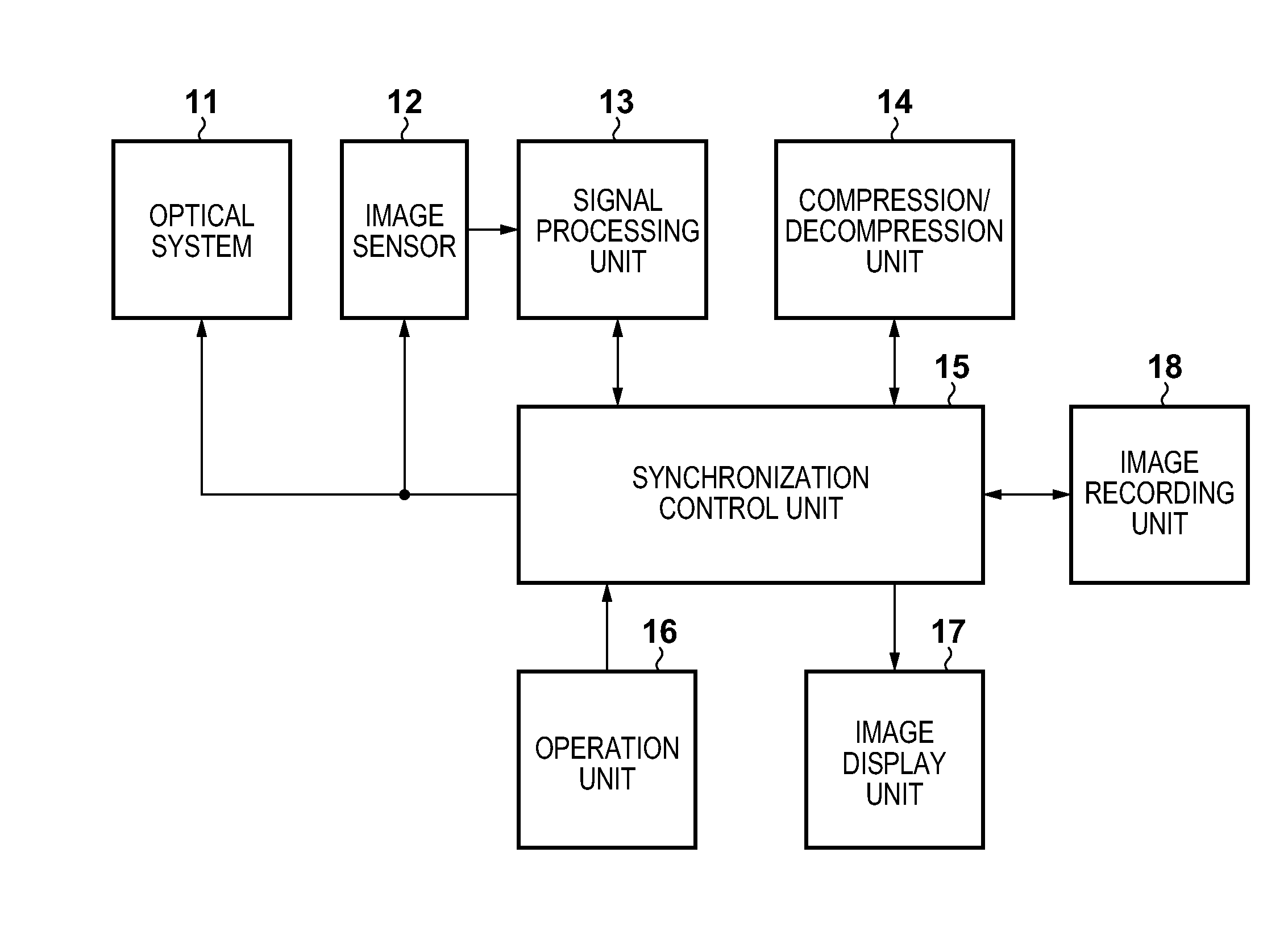
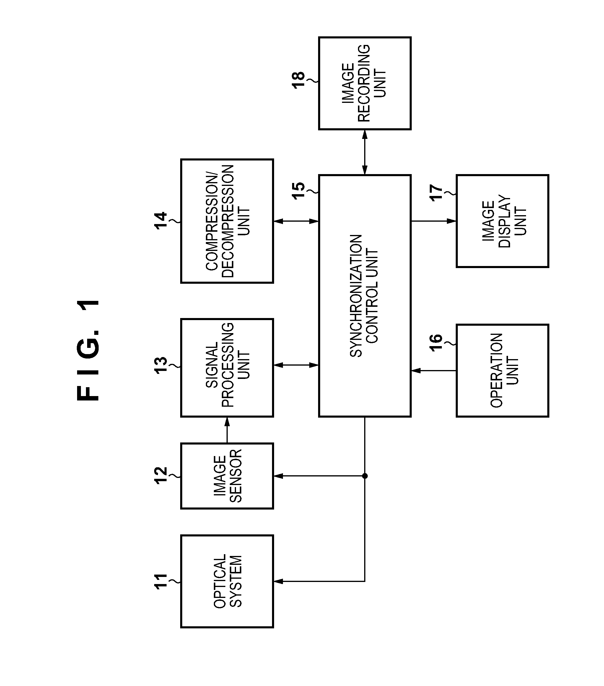
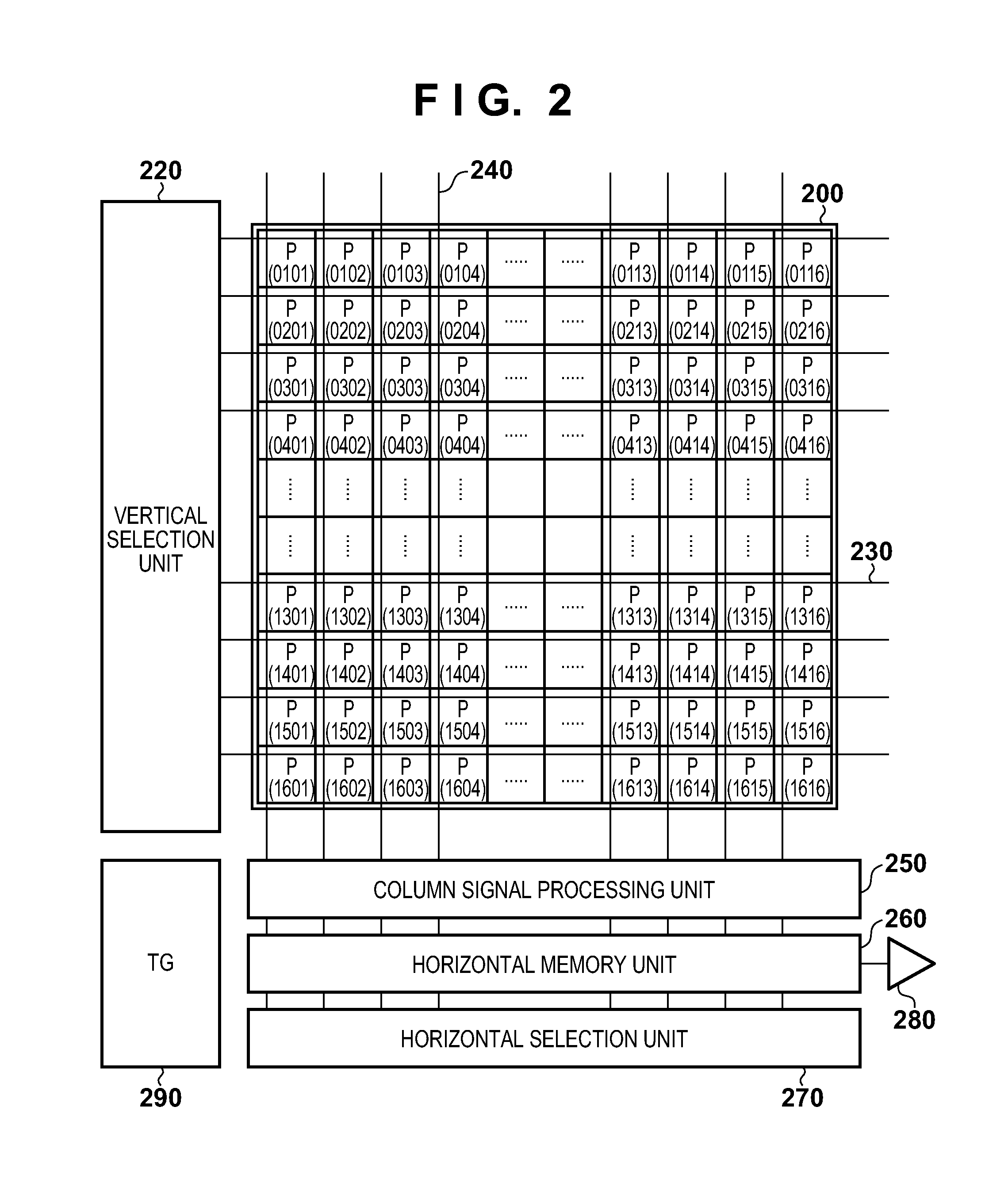
[0038]FIG. 1 is a block diagram showing the arrangement of an image capturing apparatus according to this embodiment. The image capturing apparatus of this embodiment is applicable to a digital still camera, digital video camera, and the like. The image capturing apparatus shown in FIG. 1 includes an optical system 11, image sensor 12, signal processing unit 13, compression / decompression unit 14, synchronization control unit 15, operation unit 16, image display unit 17, and image recording unit 18. The optical system 11 includes a lens required to focus light coming from an object onto the image sensor 12, a driving mechanism required to move the lens to attain a zoom operation and in-focus operation, a mechanica...
second embodiment
[0133]In the first embodiment, two frames, that is, a long-term exposure frame and short-term exposure frame are set to have different exposure times at 2-line intervals. In the second embodiment, by further adding a frame having a different exposure time, an image with a broader dynamic range is generated. A case will be described below wherein a middle-term exposure frame is set in addition to a long-term exposure frame and short-term exposure frame as frames having different exposure times at 2-line intervals. Note that in this embodiment, the basic arrangement and operation of an image capturing apparatus and those of an image sensor are the same as those in the first embodiment. Therefore, in this embodiment, FIGS. 1 and 2 will also be quoted, and the same reference numerals in FIGS. 5 and 6 to be described below denote the same elements as in FIGS. 3 and 4.
[0134]FIG. 5 is a timing chart showing control timings of an image sensor 12 according to this embodiment. In this embodim...
third embodiment
[0229]The third embodiment of the present invention will be described below with reference to FIGS. 1, 2, and 7 to 9. Note that in this embodiment, the basic arrangement and operation of an image capturing apparatus and those of an image sensor are the same as those in the first embodiment, and the following description will be given by quoting the figures and reference numerals.
[0230]In the first embodiment, two frames, that is, a long-term exposure frame and short-term exposure frame are set to have different exposure times at 2-line intervals to generate an image with a broad dynamic range. In this embodiment, a case will be described wherein a plurality of short-term exposure frames are set in a long-term exposure frame.
[0231]FIG. 7 is a timing chart showing control timings of long-term exposure lines and short-term exposure lines according to this embodiment. Referring to FIG. 7, VDL represents a vertical synchronizing signal (long-term vertical synchronizing signal) for a long...
PUM
 Abstract
Description
Claims
Application Information
 - R&D
- Intellectual Property
- Life Sciences
- Materials
- Tech Scout
- Unparalleled Data Quality
- Higher Quality Content
- 60% Fewer Hallucinations
Browse by: Latest US Patents, China's latest patents, Technical Efficacy Thesaurus, Application Domain, Technology Topic, Popular Technical Reports.
© 2025 PatSnap. All rights reserved.Legal|Privacy policy|Modern Slavery Act Transparency Statement|Sitemap|About US| Contact US: help@patsnap.com


