
Lens assembly applicable to an image sensor

Inactive Publication Date: 2014-08-07
POWER LENS TECH
View PDF0 Cites 5 Cited by
  • Summary
  • Abstract
  • Description
  • Claims
  • Application Information

AI Technical Summary

Benefits of technology

The present invention provides a practical design for a lens assembly that reduces the size of the overall optical system and improves image quality by correcting astigmatism and distortion. This lens assembly consists of two lens elements that are smaller in size and can be used in an image sensor. The result is a higher quality image that meets the requirements for 1080P sensors.

Problems solved by technology

However, such a lens system requires a longer total track length.

Method used


Image

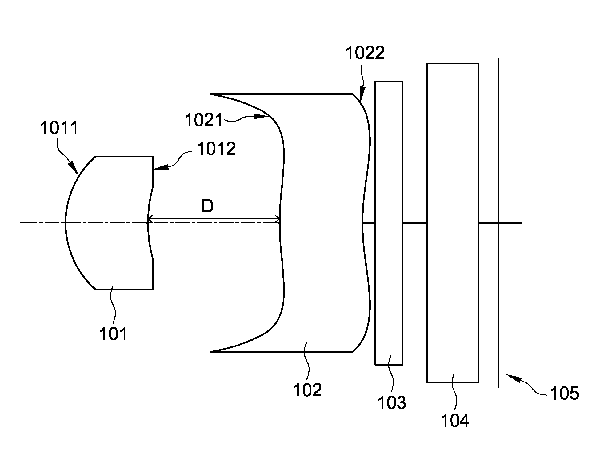
  • Lens assembly applicable to an image sensor
  • Lens assembly applicable to an image sensor
  • Lens assembly applicable to an image sensor

Examples


first embodiment

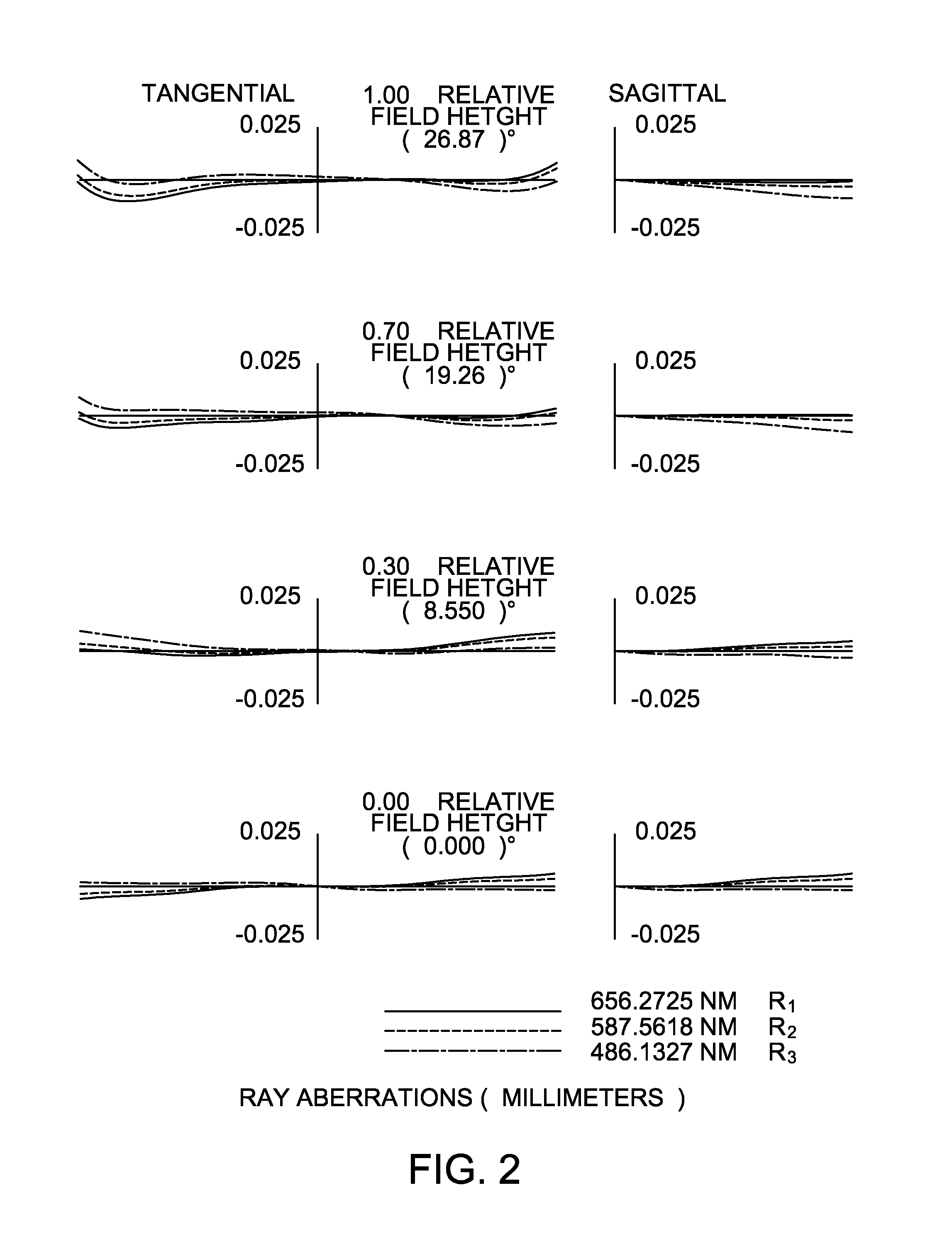
[0050]As stated above, the lens assembly 10 in accordance with the present invention provides high image quality (HFOV=26.8653°).

[0051]FIG. 4 shows ray aberration curves of the second embodiment of the present invention and FIG. 5 shows astigmatism, distortion and longitudinal spherical aberration measurements of the second embodiment of the present invention. The detailed optical data of the second embodiment is shown in the Table 3, and the aspheric surface data is shown in Table 4.

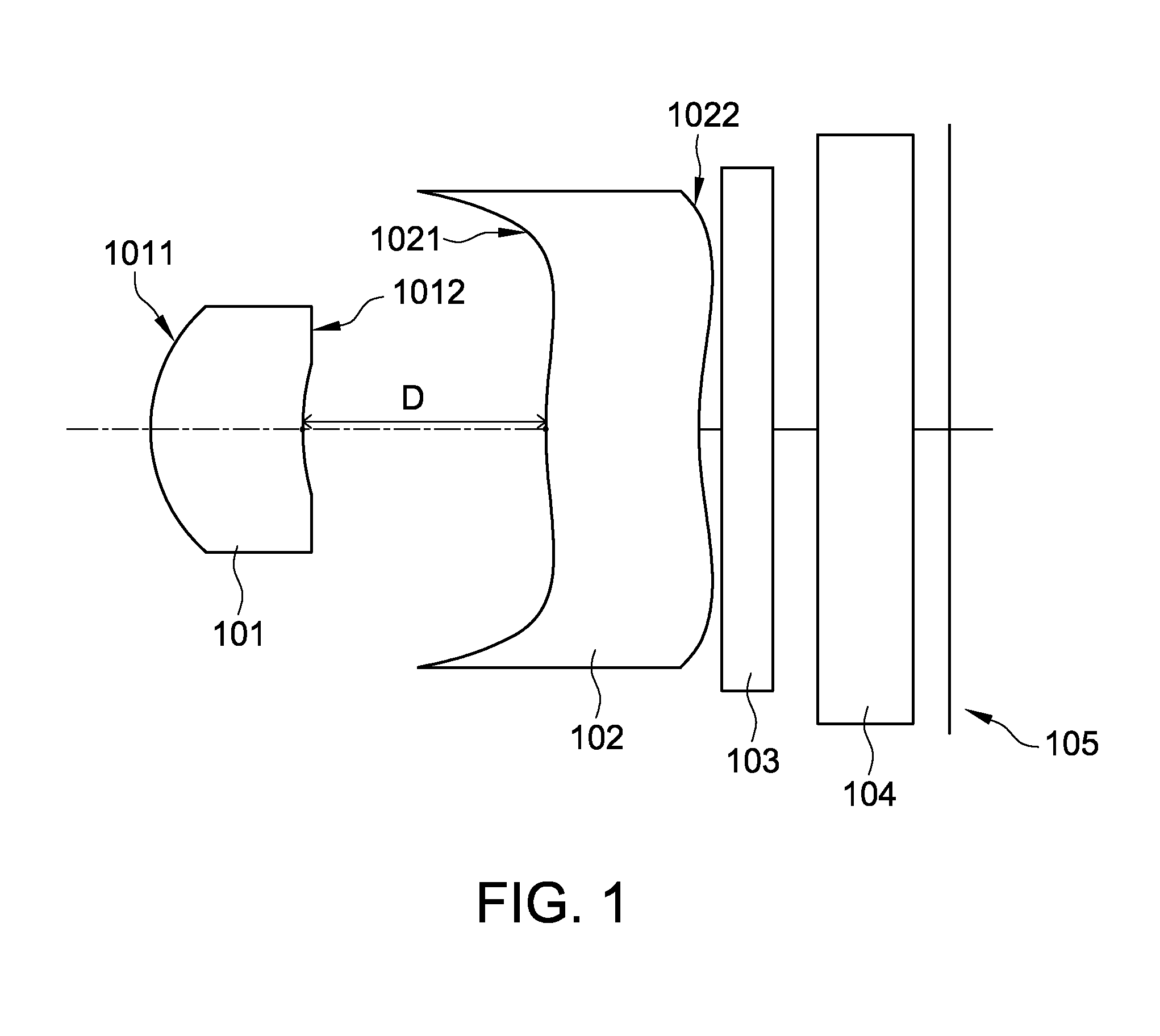
TABLE 3Lens DataΦ = 3.084F / # = 2.8f = 3.0453HFOV = 26.5512°Surf. No.rdNdVdObject side of the first0.98420.71051.515 57lens 101Image side of the first1.80011.0600——lens 101Object side of the second2.38020.59181.49  55.3lens 102Image side of the second1.97750.1206——lens 102Object side of the filter∞0.211.523155103Image side of the filter∞0.2——103Object side of the∞0.41.5168   64.16641protective glass sheet 104Image side of the∞0.157——protective glass sheet 104

TABLE 4Surf. No.Parameters of aspheric surface...

second embodiment

[0054]As stated above, the lens assembly 10 in accordance with the present invention provides high image quality (HFOV=26.5512°).

[0055]FIG. 6 shows ray aberration curves of the third embodiment of the present invention and FIG. 7 shows astigmatism, distortion and longitudinal spherical aberration measurements of the third embodiment of the present invention. The detailed optical data of the third embodiment is shown in the Table 5, and the aspheric surface data is shown in Table 6.

TABLE 5Lens DataΦ = 3.084F / # = 2.8f = 3.022HFOV = 26.7372°Surf. No.RdNdVdObject side of the first0.99250.68941.53 56lens 101Image side of the first1.79061.0417——lens 101Object side of the second2.67510.64021.515 57lens 102Image side of the second2.23350.1——lens 102Object side of the filter∞0.211.523155103Image side of the filter∞0.2——103Object side of the∞0.41.5168   64.16641protective glass sheet 104Image side of the∞0.157——protective glass sheet 104

TABLE 6Surf. No.Parameters of aspheric surfacesObject si...

third embodiment

[0058]As stated above, the lens assembly 10 in accordance with the present invention provides high image quality (HFOV=26.7372°).


PUM


Abstract

A lens assembly includes a first lens including a first convex surface facing the object side, a first concave surface with an aperture stop facing the image side; a second lens including a second convex surface facing the object side and a second concave surface facing the image side; a first lens further including. Defining that f, f1, f2 are a focal length of the lens assembly, the first lens, and the second lens; D is a distance between the first lens and the second lens; TTL is a total track length; R1 is a radius of the first convex surface; R2 is a radius of the first concave surface; R3 and R4 are respectively radius of the second convex surface and the second concave surface; and Φ is the image circle; the following conditions are satisfied: 0.01<|f / f2|<0.2; 0.1<R1 / f1<0.5; 0.8<f1 / TTL<1.1; 0.2<D / f<0.5; 0.3<R2 / Φ<0.7; and 0.03<(R3−R4) / (R3+R4)<0.3.

Description

BACKGROUND OF THE INVENTION[0001]1. Field of the Invention[0002]The present invention relates to a lens assembly applicable to an image sensor, and more particularly to a lens assembly applicable to an image sensor composes of two lens elements; and such lens assembly has the features of smaller size and image quality with well corrected aberration.[0003]2. Related Art[0004]In recent years, as digital imaging technology and production process technology of electronic components continue to evolve, a digital imaging lens not is only used in digital camera-related products, but also becomes indispensable equipment in Tablet computers, laptops or smart phones, and other porTable electronic devices.[0005]At the same time, the demand with smaller size for a porTable electronic device has grown remarkably and an imaging lens used in such a porTable electronic device also needs to be miniaturized. As a production process on the complementary metal-oxide semiconductor (CMOS) and the charge-...

Claims


Application Information

Patent Timeline
IPC IPC(8): G02B9/10G02B13/00
CPCG02B13/003G02B9/10
Inventor YEH, YI CHAOCHERN, JYH LONG
Owner POWER LENS TECH
Learn More