Endoscope system and image generation method

an endoscope and image technology, applied in image enhancement, image analysis, medical science, etc., can solve the problems of difficult to accurately grasp the shape or the size of irregular patterns, image is not suitable for diagnosis,

Active Publication Date: 2014-08-07
FUJIFILM CORP
View PDF16 Cites 3 Cited by
  • Summary
  • Abstract
  • Description
  • Claims
  • Application Information

AI Technical Summary

Benefits of technology

[0010]It is an object of the present invention to provide an endoscope system and an image generation ...

Problems solved by technology

Therefore, since an image obtained in a situation where the distance from an observation region is great as in a distant-view state becomes a dark image with the reduced amount of light, the image is not suitable for diagnosis.
In addition, according to the method disclosed in...

Method used


Image

  • Endoscope system and image generation method
  • Endoscope system and image generation method
  • Endoscope system and image generation method

Examples


first embodiment

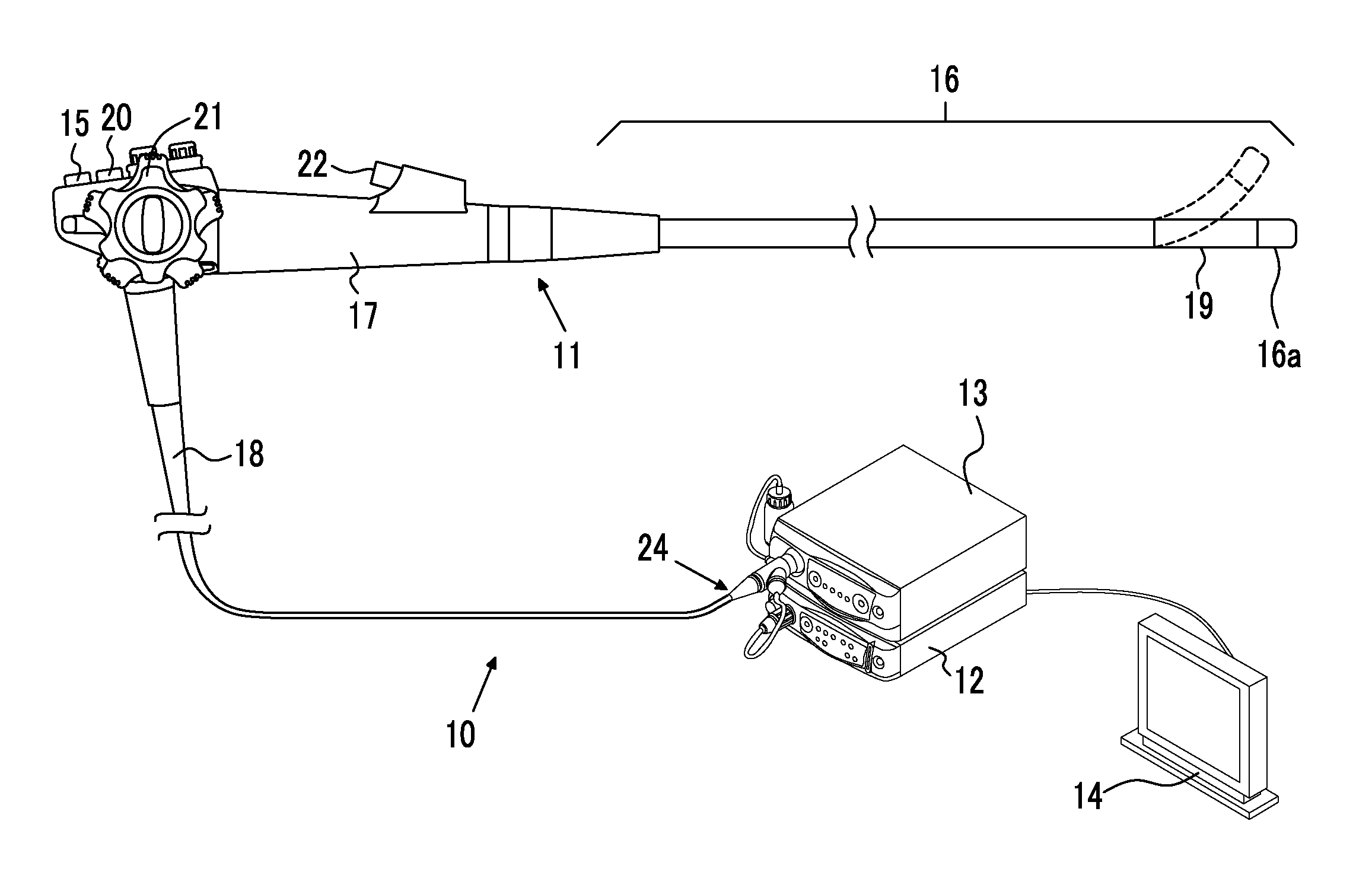
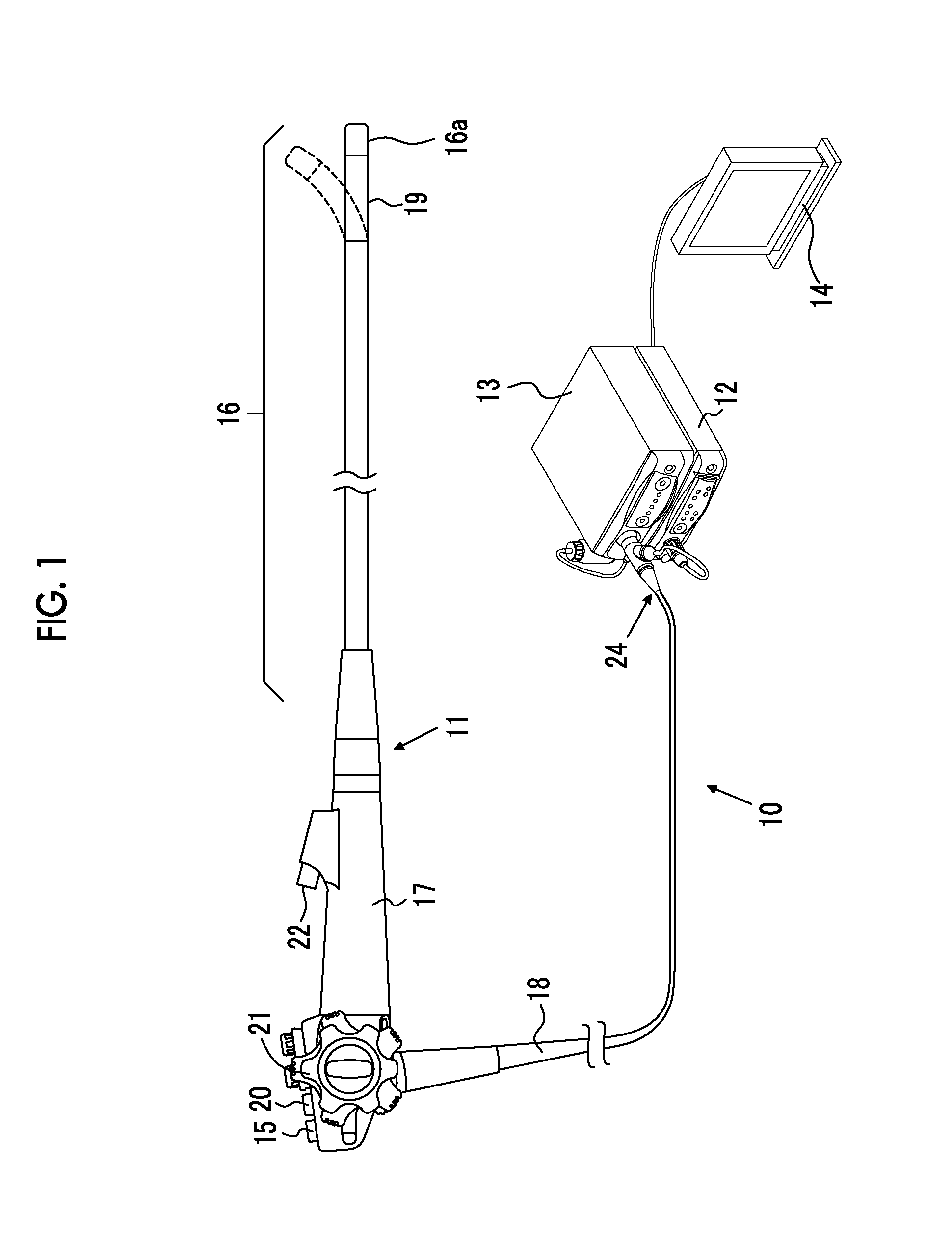
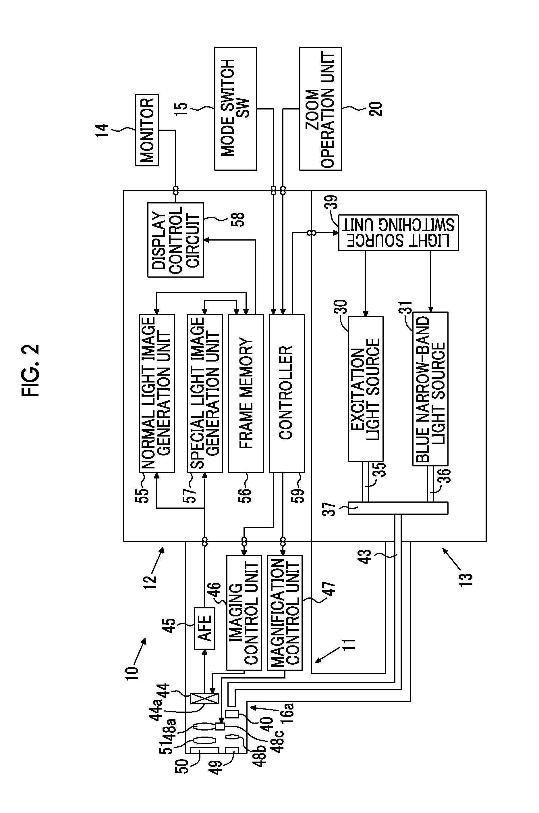
[0044]As shown in FIGS. 1 and 2, en endoscope system 10 of the first embodiment includes: an electronic endoscope 11 (a form of image signal acquisition unit) that images the inside of a subject, a processor device 12 that performs various kinds of image processing on the image captured by the electronic endoscope 11; a light source device 13 that supplies light for illuminating the subject to the electronic endoscope 11; and a monitor 14 that displays an image after various kinds of image processing are performed by the processor device 12.

[0045]The electronic endoscope 11 includes a flexible insertion unit 16 that is inserted into the subject, an operating unit 17 provided at the proximal end of the insertion unit 16, and a universal code 18 that makes a connection between the operating unit 17 and the processor device 12 and the light source device 13. A curved portion 19 obtained by connecting a plurality of curved pieces is formed at the distal end of the insertion unit 16. The...

second embodiment

[0097]In the second embodiment, when generating a normal light image in the microstructure observation mode and the microstructure and blood vessel observation mode, a correction signal generation section 55a in the normal light image generation unit 55 generates a correction signal B′ by removing the component of the blue narrow-band light BN from the frame sequential imaging signal B+BM, and generates a normal light image using the correction signal B′ and the frame sequential imaging signals G and R. The correction signal generation section 55a generates the correction signal B′ by multiplying the frame sequential imaging signal B+BN by a correction coefficient k that is determined in advance from the relationship between the amount of light of B color and the amount of blue narrow-band light BN or the like.

[0098]In the first and second embodiments described above, a pixel region where the pixel value exceeds the threshold value Th1 of the brightness signal I is set as the superf...


PUM


Abstract

A blue signal B, a green signal G, and a red signal R are obtained by imagining a subject illuminated with white light W using a color CCD 44. Based on these signals B, G, and R, a normal light image in which a wavelength component of a visible light region is included is generated. Based on the signals B, G, and R, a brightness signal I ((B+G+R)/3) showing the average brightness of the subject is generated. A pixel region exceeding the fixed threshold value Th1 of the brightness signal I is extracted as a superficial microstructure P, such as a pit pattern. A microstructure enhancement image 72 is generated by combining the normal light image with a superficial microstructure image 70 obtained by extracting the superficial microstructure P. The generated microstructure and blood vessel enhancement image 72 is displayed on a monitor 14.

Description

CROSS REFERENCE TO RELATED APPLICATIONS[0001]This application is a Continuation of PCT International Application No. PCT / JP2012 / 076298 filed on Oct. 11, 2012, which claims priority under 35 U.S.C. §119(a) to patent application Ser. No. 2011-225140 filed in Japan on Oct. 12, 2011 and patent application Ser. No. 2012-193907 filed in Japan on Sep. 4, 2012, all of which are hereby expressly incorporated by reference into the present application.BACKGROUND OF THE INVENTION[0002]1. Field of the Invention[0003]The present invention relates to an endoscope system capable of clearly observing a blood vessel pattern such as a superficial microvessel, a microstructure such as a pit pattern, or an irregular pattern such as hypertrophy, and an image generation method.[0004]2. Description of the Related Art[0005]In recent medical treatment, diagnosis or the like using an endoscope apparatus has been widely performed. In this endoscopic diagnosis, not only normal light observation, in which white ...

Claims


Application Information

Patent Timeline
IPC IPC(8): A61B1/06A61B1/05
CPCA61B1/05A61B1/0638G06T5/50G06T2207/10068G06T2207/10152G06T2207/20221G06T2207/10024A61B1/0653G06T7/11G06T7/136A61B1/000094
Inventor YAMAGUCHI, HIROSHIOZAWA, SATOSHIIIDA, TAKAYUKI
Owner FUJIFILM CORP
Why Eureka
Try Eureka