
Filter medium for air filter and filter unit

a filter medium and air filter technology, applied in the direction of filtration separation, separation process, synthetic resin layered products, etc., can solve the problems of increasing the pressure loss a heavy dust load, so as to maintain the dust collection efficiency, reduce the pressure loss, and reduce the weight of the air filter unit.

Active Publication Date: 2014-08-14
DAIKIN IND LTD
View PDF5 Cites 26 Cited by
  • Summary
  • Abstract
  • Description
  • Claims
  • Application Information

AI Technical Summary

Benefits of technology

The patent describes a filter medium and air filter unit that can collect dust more efficiently without increasing the weight of the unit. This results in a filter that can maintain its effectiveness while also reducing the pressure drop.

Problems solved by technology

On the other hand, clogging due to dust occurs frequently in a porous PTFE film, which has a fiber structure denser than that of a glass fiber filter medium that has been used conventionally, and pressure loss of an air filter unit increases in a short time when the air filter unit is used in an environment, which gives a heavy dust load, such as an outside air processing unit.

Method used

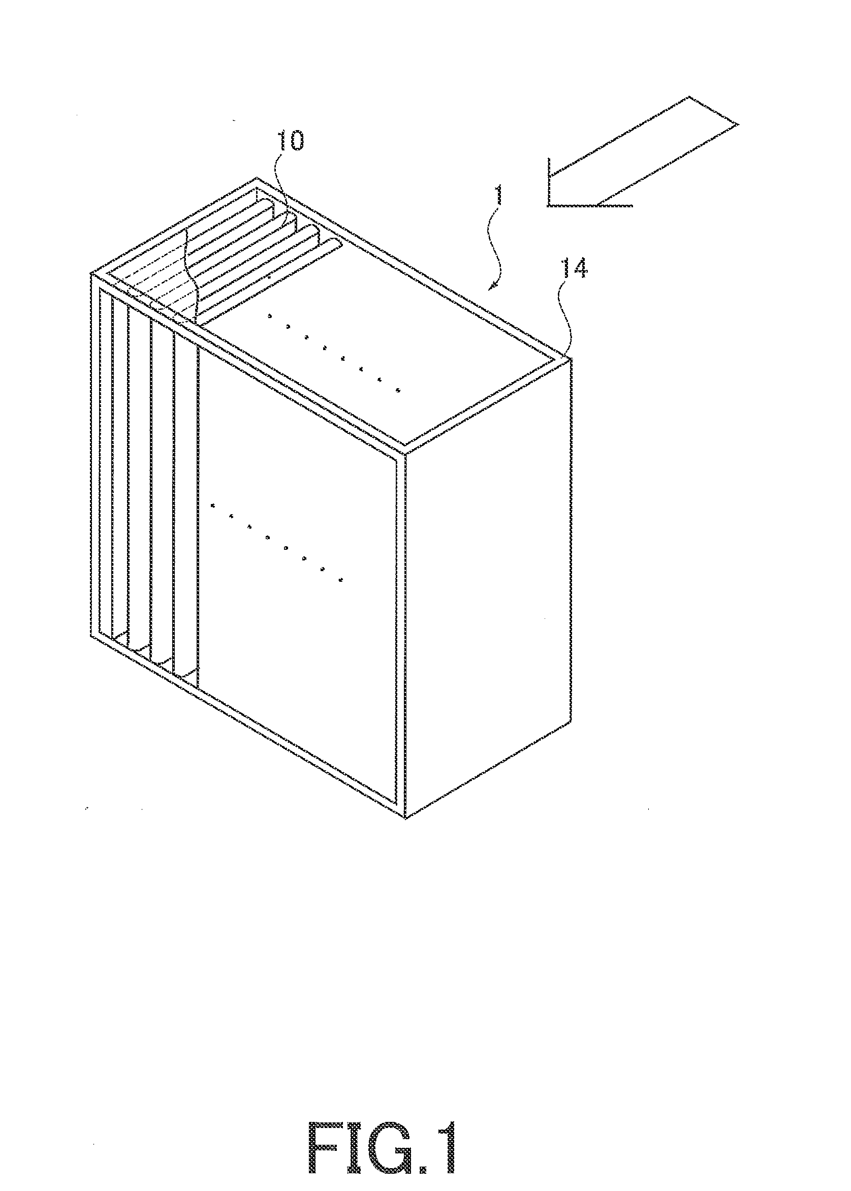
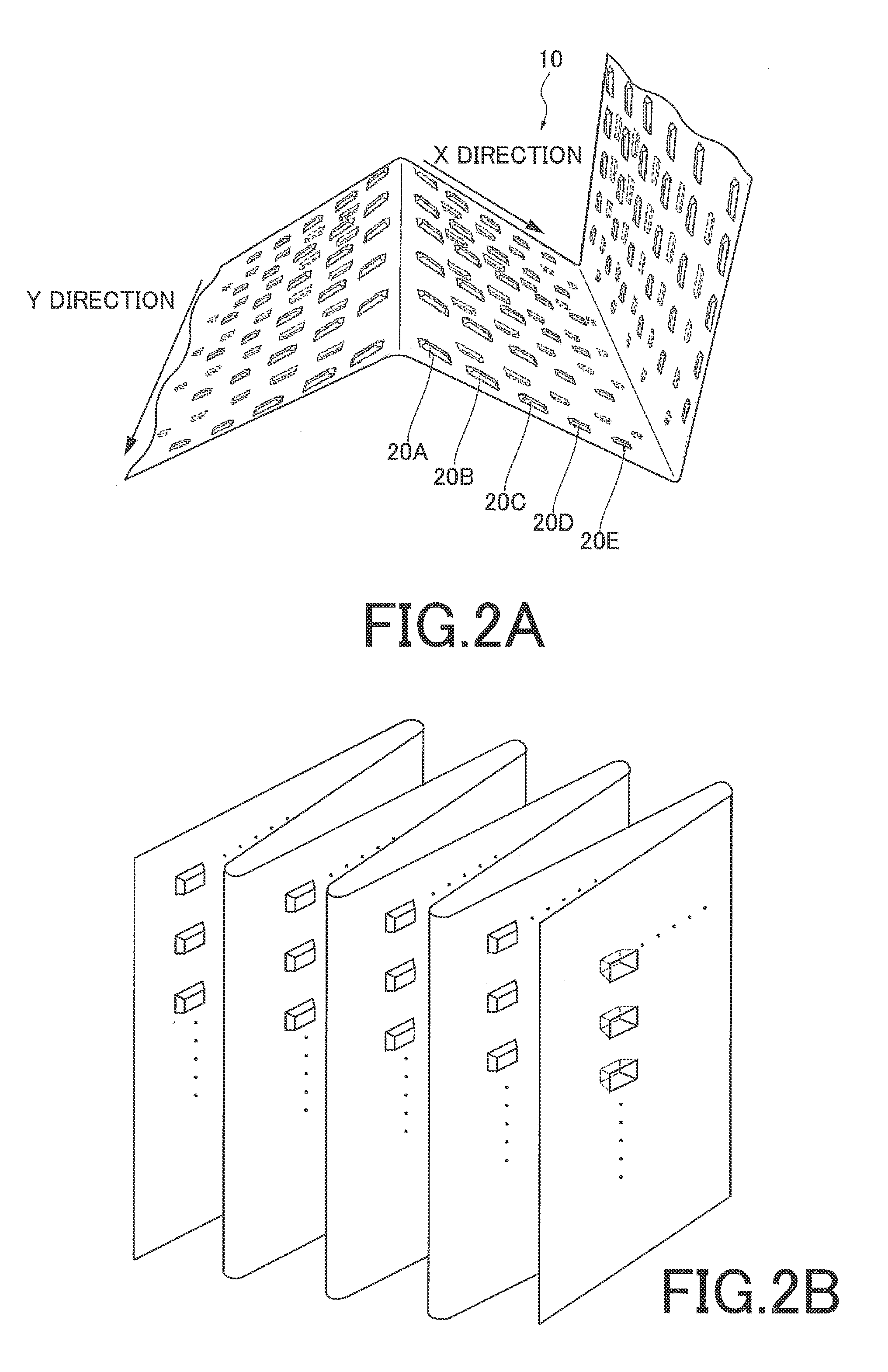

Image

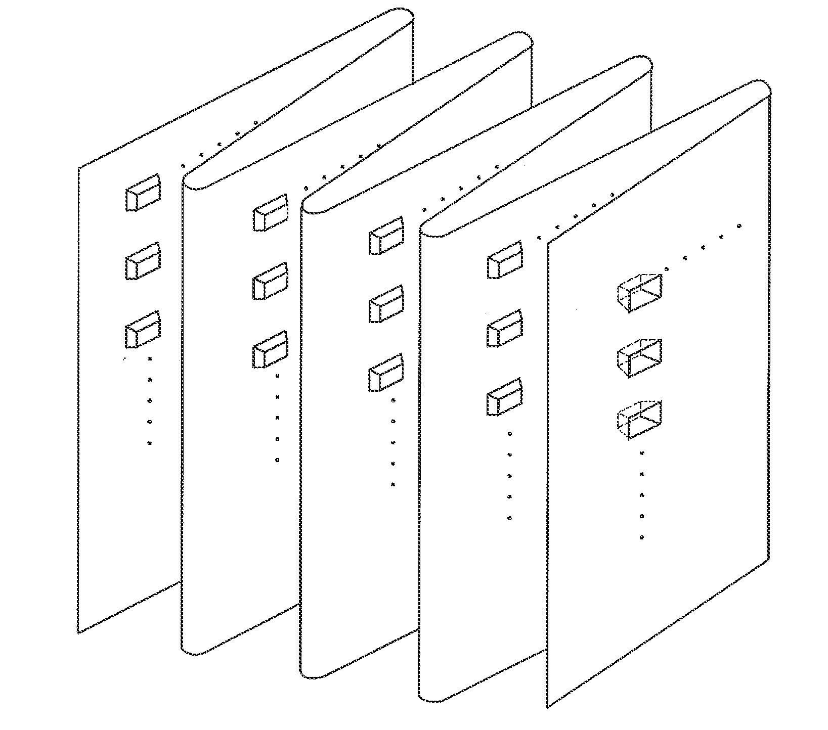
  • Filter medium for air filter and filter unit
  • Filter medium for air filter and filter unit
  • Filter medium for air filter and filter unit

Examples


modified embodiment

[0066]As illustrated in FIG. 4, the filter medium 10 of the present embodiment is provided with the air-permeable support layer 26 at a downstream side of an air flow of the principal collection layer 22. As illustrated in FIG. 5, the filter medium 10 of the present modified embodiment is provided with an air-permeable support layer 26 at a downstream side of an air flow of the principal collection layer 22 and also an air-permeable support layer 28 at an upstream side of an air flow of the principal collection layer 22. That is, regarding the filter medium 10 of the present modified embodiment, the air-permeable cover layer 24, the pre-collection layer 20, the air-permeable support layer 28, the principal collection layer 22 and the air-permeable support layer 26 are laminated in this order from an upstream side of an air flow. The air-permeable support layer 28 may have a structure similar to that of the air-permeable support layer 26, or may have a different structure. The pressu...

example

[0088]In order to check the effect of the present embodiment, a filter unit provided with the following filter medium was prepared (Samples 1 to 9).

[0089](Sample 1)

[0090]Preparation of Principal Collection Layer 22 (Porous PTFE Film)

[0091]Hydrocarbon oil (“IP SOLVENT 2028” manufactured by IDEMITSU KOSAN CO., LTD.) of 33.5% by mass at 20° C. was added as an extruded liquid lubricant per 1 kg of PTFE fine powder (“POLYFLON FINE POWDER F106” manufactured by Daikin Industries, Ltd.) having a mean molecular weight of 6,500,000 and was mixed. Next, the obtained mixture was extruded using a paste extruding device to obtain a compact having a round-bar shape. The molded body having a round-bar shape was shaped into a film form by a calendar roll heated to 70° C. so as to obtain a PTFE film. The film is carried through a hot-air drying furnace of 250° C. to vaporize and remove hydrocarbon oil so as to obtain an unbaked PTFE film having a band form with a mean width of 150 mm. Next, the unbak...


PUM

PropertyMeasurementUnit
pressure lossaaaaaaaaaa

Abstract

A filter medium for an air filter collecting dust in an air flow has a principal collection layer including a porous polytetrafluoroethylene film. A surface of the filter medium is provided with a plurality of embossed projections. Preferably, a processed filter medium maintains a zigzag shape by pleating an unprocessed filter medium to create mountain folds and valley folds. Preferably, an air filter unit includes such a processed filter medium and a frame body holding the processed filter medium.

Description

TECHNICAL FIELD[0001]The present invention relates to a filter medium for an air filter, and an air filter unit for collecting dust in an air flow.BACKGROUND ART[0002]A semiconductor device or a liquid crystal display has been conventionally manufactured in high clean space. To produce such high clean space, a porous film (which will be hereinafter referred to as a porous PTFE film) made of polytetrafluoroethylene (which will be hereinafter referred to as PTFE) is used as a dust collecting filter. A porous PTFE film, which has high dust collection efficiency compared with a filter medium made of glass fiber at the same pressure loss, is favorably used especially for a HEPA filter (High Efficiency Particulate Air Filter) or a ULPA filter (Ultra Low Penetration Air Filter).[0003]On the other hand, clogging due to dust occurs frequently in a porous PTFE film, which has a fiber structure denser than that of a glass fiber filter medium that has been used conventionally, and pressure loss...

Claims


Application Information

Patent Timeline
Patent Type & Authority Applications(United States)
IPC IPC(8): B01D46/52
CPCB01D46/54B01D46/52B32B5/24B01D39/16B01D46/543B32B27/30B01D46/523B01D46/521D06M17/00B01D39/1623B01D39/1692B32B5/022B32B5/26B32B7/12B32B2262/0238B32B2262/0253B32B2262/0261B32B2262/0284B32B2262/0292B32B2307/724
Inventor BAO, LIKOBAYASHI, MAKOTOMORITA, JUNSAKANO, TATSUMIKITAYAMA, OSAMUHARA, SATOSHINIINUMA, HITOSHI
Owner DAIKIN IND LTD
Learn More