Filling of storage containers with a gaseous pressurised medium

a technology of gaseous gaseous medium and storage container, which is applied in the direction of container filling under pressure, liquid handling, transportation and packaging, etc. it can solve the problems of adversely affecting the energy consumption of the cooling system, unfavorable effect on costs and also on the susceptibility of the cooling system to damage, etc., and achieves improved pulsation and reduced enthalpy range. , the effect of increasing the precision

Inactive Publication Date: 2014-08-14
LINDE AG
View PDF72 Cites 11 Cited by
  • Summary
  • Abstract
  • Description
  • Claims
  • Application Information

AI Technical Summary

Benefits of technology

[0016]Furthermore, said throttle can be controlled in such a way that said pulsation is improved in the at least one heat transfer medium, i.e. that the enthalpy range is reduced. In other words, the filling process thus approaches an ideal isenthalpic process. The method can of course also be carried out with a fixed throttle.
[0017]As a result, the final temperature of the filling procedure, i.e. of the medium, can be better determined using the method according to the invention, and more precisely by calculating an isenthalpic filling; the previously employed polytopic filling is replaced by an isenthalpic one. Especially in the critical area (filling of an empty vehicle tank), the precision can be increased enormously on account of the isenthalpic filling instead of an isentropic filling.
[0018]Furthermore, the cooling efficiency is also increased by the enthalpy-dependent pulsation in the at least one heat transfer medium. It is thus possible to work with a smaller temperature gradient between the cooling media.

Problems solved by technology

The cooling system required for this necessitates a relatively large amount of installation space and energy, which depending on the arrangement in the filling station can have an unfavourable effect on costs and also on the susceptibility of the cooling system to damage.
Since hydrogen continuously flows through such a cooling system while said pressure ramp is being passed through, such cooling systems have to operate with a relatively high temperature reduction in order to bring about the desired cooling of the hydrogen at the filling station, which adversely impacts on the energy consumption of this cooling system.

Method used


Image

  • Filling of storage containers with a gaseous pressurised medium
  • Filling of storage containers with a gaseous pressurised medium

Examples


Embodiment Construction

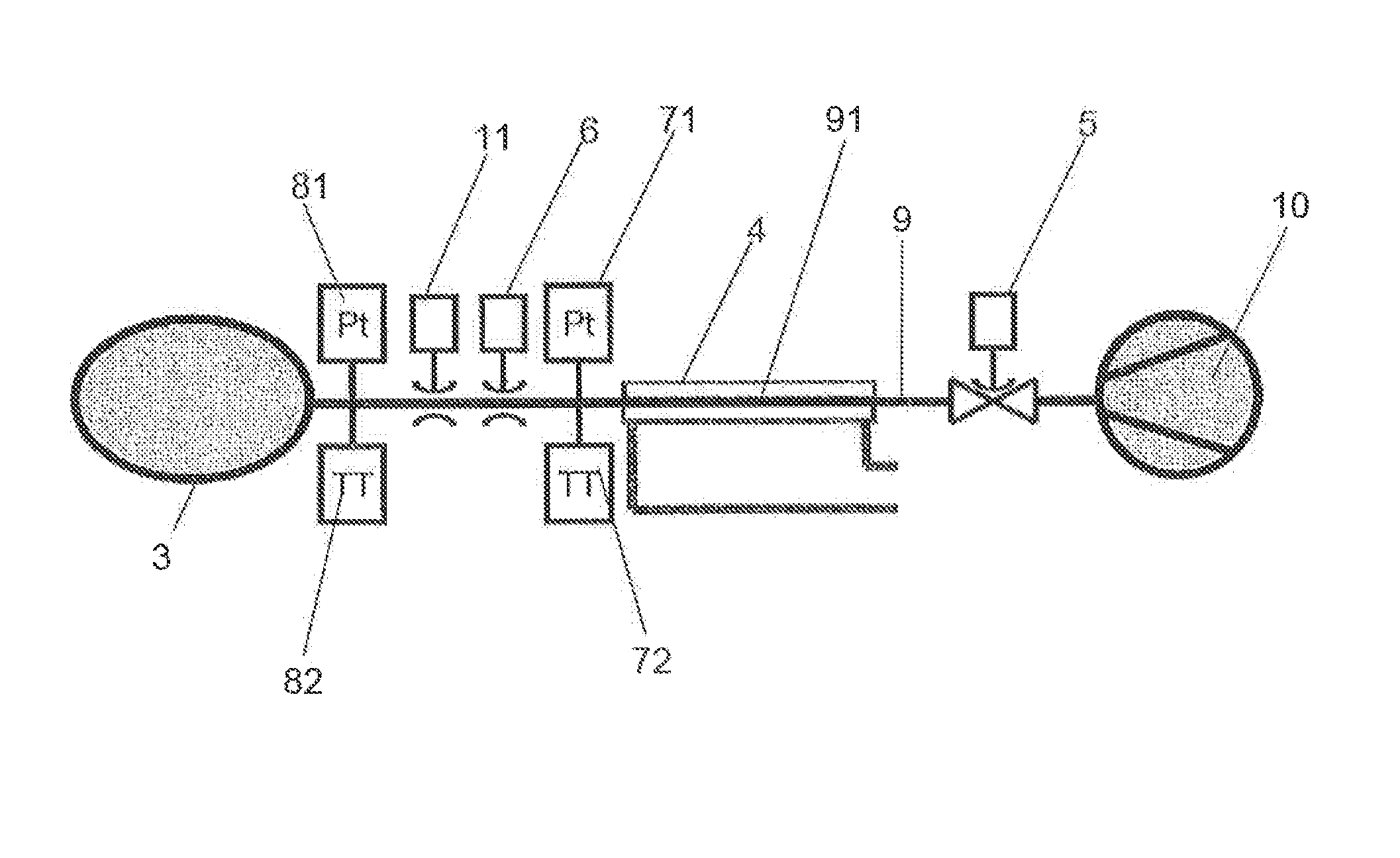
[0023]FIG. 1 shows a refuelling facility 1 for refuelling a storage container 3 in the form of a vehicle tank which can be connected to a tank supply line 9. Hydrogen is conveyed via a compressor 10 and a controllable valve 5 disposed downstream of compressor 10 into a first heat transfer medium 4, which cools a section or a known volume 91 of tank supply line 9. Heat transfer medium 4 is preferably formed by a thermoblock, which surrounds or constitutes said volume 91 of tank supply line 9 and is cooled by means of a cooling circuit. The thermoblock is preferably made of aluminium (so-called aluminium cold fill). The hydrogen is cooled to a specific temperature by means of heat transfer medium 4. Provided downstream of heat transfer medium 4 is a pressure sensor and a temperature sensor 71, 72, which ascertain the pressure and respectively the temperature of the hydrogen upstream of an, in particular, controllable throttle 6. Disposed downstream of throttle 6 is a mass flow measuri...


PUM


Abstract

The invention relates to a method for refuelling a storage container with a pressurised gaseous medium, in particular hydrogen, wherein this medium is introduced into the storage container via a tank supply line, wherein the temperature of the medium upon entry into the storage container and the pressure in the storage container are controlled in such a way that the enthalpy of the medium introduced into the storage container fluctuates within a preset enthalpy range or is constant.

Description

CROSS REFERENCE TO RELATED APPLICATIONS[0001]This application claims priority from German patent application DE 102013002431.5 filed Feb. 12, 2013.BACKGROUND OF THE INVENTION[0002]The invention relates to a method for filling a storage container with a pressurised gaseous medium, in particular hydrogen.[0003]For the refuelling of vehicles with gaseous hydrogen as a fuel, specially designed filling stations are required, which meet technical and safety requirements essential for the refuelling. Thus, for example, provision can be made such that the hydrogen is intended to be conveyed within three minutes into a storage container designed for the purpose (e.g. vehicle tank) and brought to a pressure of 700 bar, without the temperature in the storage container thereby rising over 85° C. and without the temperature of the hydrogen falling below −40° C.[0004]Before the start of the refuelling procedure, a pressure and tightness test is usually carried out (e.g. according to standard SAE ...

Claims


Application Information

Patent Timeline
Patent Type & Authority Applications(United States)
IPC IPC(8): F17C5/06
CPCF17C5/06F17C5/007F17C2205/0326F17C2221/012F17C2223/0123F17C2223/035F17C2225/0123F17C2225/036F17C2227/0157F17C2227/0337F17C2227/036F17C2227/039F17C2250/032F17C2250/043F17C2250/0439F17C2250/0443F17C2250/0626F17C2250/0631F17C2260/023F17C2265/065F17C2270/0139Y02E60/32
Inventor ADLER, ROBERTDOMER, SASCHASIEBERT, GEORG
Owner LINDE AG
Why Eureka
Try Eureka