
Sprayer

a technology of sprayer and nozzle, which is applied in the field of sprayer, can solve the problems of increasing the size and weight of the product, difficult to provide economical advantages, and difficult to clean the fine slit rotor, ultrasonic transducer, etc., and achieves the effect of effectively atomizing a disinfectant and large spraying area

Inactive Publication Date: 2014-08-14
BAEK HYE SUN
View PDF0 Cites 6 Cited by
  • Summary
  • Abstract
  • Description
  • Claims
  • Application Information

AI Technical Summary

Benefits of technology

The patent text has a technical effect that needs to be understood. The technical effects are related to the invention itself and its methods of use. This invention has specific technical effects that make it different from other inventions and provide better performance and efficiency.

Problems solved by technology

However, the hydraulic sprayer generally makes use of an internal combustion engine for operating a plunger and further needs a compression controlling mechanism and a pressure tank, thus increasing the size and weight of the product and making it hard to provide economical advantages.
Further, the rotary sprayer and the ultrasonic sprayer are low in weight and compact in configuration, but generally, since disinfectant or pesticide is toxic and corrosive, it is hard to clean the fine slit rotor, ultrasonic transducer, or the baffles on which the fine slits are formed to form ultrasound.
Furthermore, they will be likely to be corrosive.
However, the mean diameters of the macro particles in the range between 20 μm and 200 μm through atomization are substantially large, so that the disinfectant or the environment improving agent is used in relatively large quantities, thus failing to provide economical advantages and causing soil or dwelling environment to be polluted and poisoned through the use of the excessive quantity.
Besides, the atomization is not gently conducted, so that the disinfectant or environment improving agent cannot be uniformly permeated and accessed to an object to be disinfected through the atomization, thus providing low work efficiency.
In more detail, since the use of Freon has been recently prohibited, the compression sprayer makes use of compressive gas like propane gas having high inflammability, thus providing low safety and further, the compression sprayer has to use a disposable container, thus failing to provide economical advantages.
The mister may cause air contamination due to the exhaust gas, and the evaporation sprayer has a relatively low efficiency.

Method used


Image

  • Sprayer
  • Sprayer
  • Sprayer

Examples


first embodiment

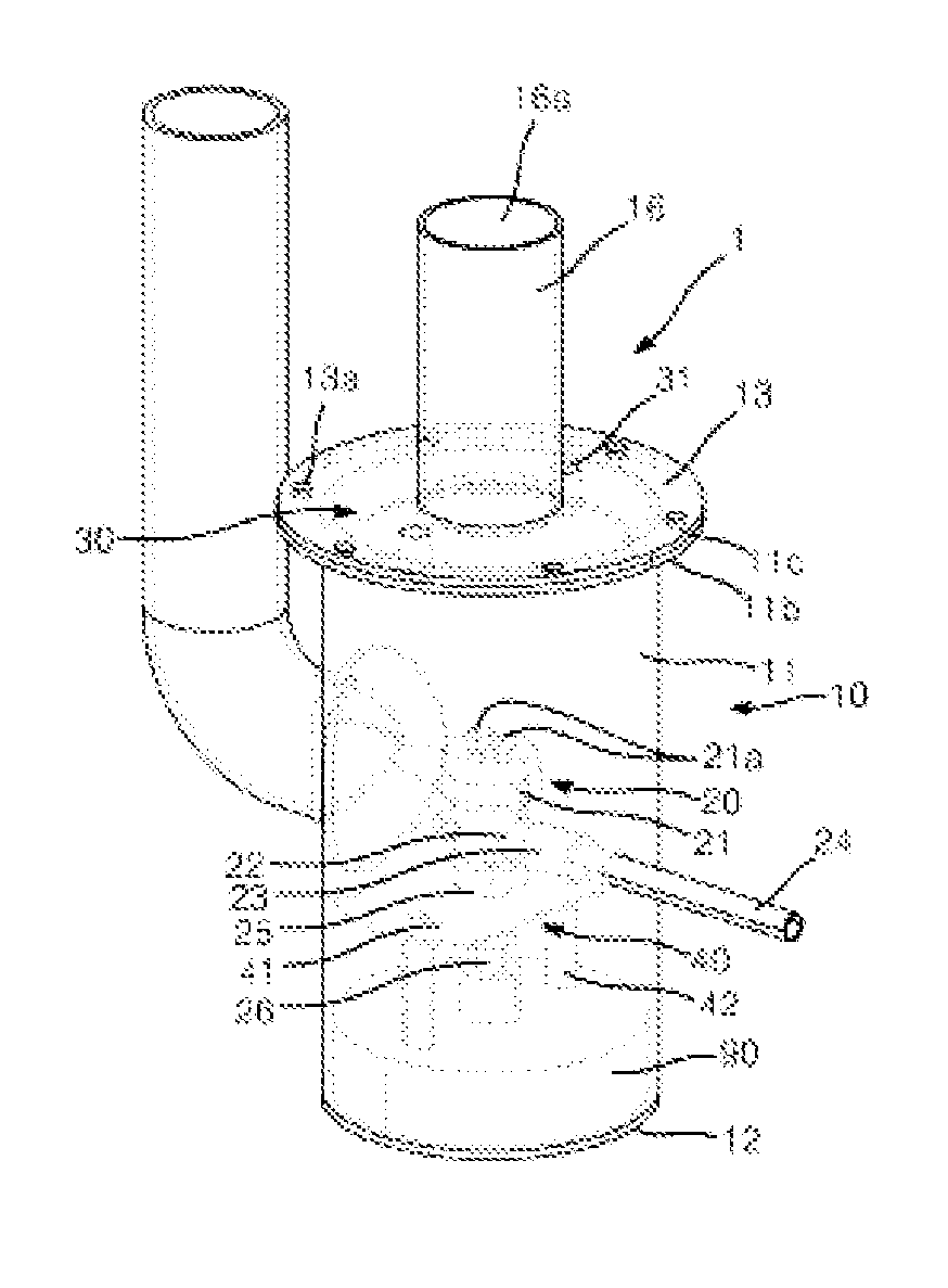
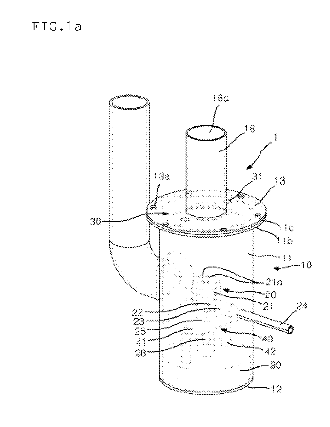
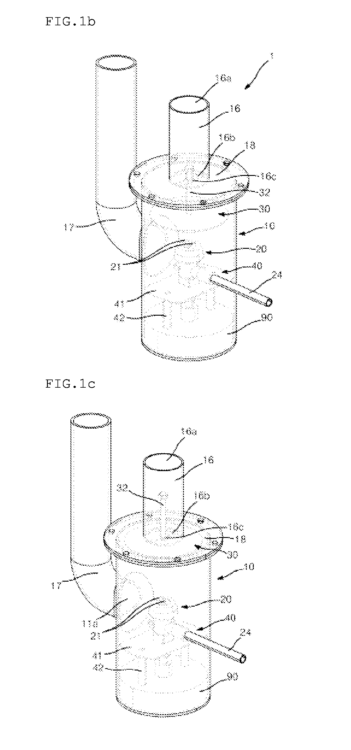
[0029]To achieve the first to fifth objects as mentioned above, according to the present invention, the sprayer is configured wherein the atomization member has a shape of a round plate in such a manner as to be fixed to a top surface plate communicating with a mist discharge pipe on which the mist discharge port is formed by means of a plurality of stoppers, so that the outer peripheral surface of the inner peripheral wall of the main body and the outer peripheral surface of the atomization member are spaced preferably 2 to 20 mm apart from each other, more preferably 5 to 15 mm apart from each other, and most preferably 8 to 12 mm apart from each other and further, the spaced distances between the spray nozzle and the atomization member and between the atomization member and the top surface plate are preferably in the range between 10 mm and 100 mm, more preferably in the range between 15 mm and 90 mm, and most preferably in the range between 20 mm and 80 mm.

[0030]To achieve the s...

second embodiment

[0032]To achieve the first to fifth objects as mentioned above, according to the present invention, the sprayer is configured to have a shoulder and a neck having a mist discharge port mounted on the main body and to have the atomization member having a shape of a roller, so that the ratio of the diameter of the main body to the diameter of the roller as the atomization member is in the range between 1:0.25˜0.45, and the vertical distance between a spray nozzle and the underside surface of the atomization member is preferably in the range between 10 mm and 100 mm, more preferably in the range between 15 mm and 90 mm, and most preferably in the range between 20 mm and 80 mm.

[0033]To achieve the sixth object as mentioned above, according to the second embodiment of the present invention, the sprayer is configured wherein the spray nozzle is located on the supporter and includes a head having a liquid spray part and a plurality of air spray parts and a body having an air inlet and a li...

third embodiment

[0034]To achieve the first to fifth objects as mentioned above, according to the present invention, a sprayer is configured to have a shoulder and a neck having a mist discharge port mounted on the main body and to have the atomization member having a shape of a sphere, so that through a plurality of spacers, the outer peripheral surface of the upper portion of the atomization member and the inner peripheral surface of the shoulder are spaced preferably 2 to 20 mm apart from each other, more preferably 5 to 15 mm apart from each other, and most preferably 8 to 12 mm apart from each other and further, the vertical distance between the spray nozzle and the underside surface of the atomization member is preferably in the range between 10 mm and 100 mm, more preferably in the range between 15 mm and 90 mm, and most preferably in the range between 20 mm and 80 mm.


PUM


Abstract

The present invention relates to a sprayer. The sprayer according to the present invention comprises: a vessel main body where an air intake port and a mist discharge port are formed; a spray nozzle which has an air inlet and a liquid inlet, and which is disposed inside the vessel main body; and an atomization member which collides with or diverts mist sprayed through the spray nozzle. The present invention is capable of effectively atomizing a disinfectant, pesticide, or an environment improving agent such as an air freshener or a deodorant agent in a fine particle state, and is thus economically feasible and environmentally friendly since the possibility of pollution can be reduced.

Description

BACKGROUND OF THE INVENTION[0001]1. Technical Field[0002]The present invention relates to a sprayer, and more particularly, to a sprayer that is capable of effectively atomizing a disinfectant or agricultural chemicals such as an anti-virus agent, an anti-bacterial agent, an anti-fungal agent, a pesticide and the like or an environment improving agent such as a fragrant, a deodorant agent and the like, to macro-particle sizes, and in large quantities spraying the atomized mist, so that the mist can be sprayed in a relatively small quantity upon the work for the prevention of infectious diseases or for the environment improvement, thus reducing the possibility of the pollution of soil or dwelling environment and further, the disinfectant or environment improving agent can be uniformly permeated and accessed to an object to be disinfected through the atomization, thus enhancing the work efficiency.[0003]2. Background Art[0004]Generally, sprayers are classified in various ways, but in ...

Claims


Application Information

Patent Timeline
IPC IPC(8): B05B7/04
CPCA61L9/14B05B1/02B05B1/12B05B7/0807B05B7/0416B05B7/0012A61L2/22
Inventor JEON, EUN SOOBAEK, HYE SUN
Owner BAEK HYE SUN
Learn More