Leak Detectable Geomembrane Liners and Method and Apparatus for Forming

a geomembrane lining and detection method technology, applied in the field of geomembrane linings, can solve the problems of unreliable electrical detection of leaks in the above described manner, high current density and localized anomalies, and damage to the lining, so as to maintain the overall structural integrity of the panel

Active Publication Date: 2014-08-14
GSE ENVIRONMENTAL
View PDF3 Cites 19 Cited by
  • Summary
  • Abstract
  • Description
  • Claims
  • Application Information

AI Technical Summary

Benefits of technology

[0023]In still another aspect of the present invention, a heating unit is provided for use with a heat welder and includes a wedge mountable in the heat welder between its liner slots whereby the wedge defines part of an upper wall of the lower slot and the lower wall of the upper slot, and the defined upper and lower walls taper together to a point adjacent the merged slot of the heating unit. At least one projection extends from the wedge defined lower wall of the upper slot sufficiently to separate or interrupt a bottom portion of a liner panel passing through the upper slot over the projection while still maintaining the overall structural integrity of the panel.

Problems solved by technology

Generally, these liners are made of insulating material (such as high density polyethylene) which, even if thoroughly tested to be defect free when shipped, can be damaged during shipping and / or installation by, for example, heavy equipment, cutting tools, welding equipment, animals, and vandalism, necessitating that a final leak check be conducted after the liner is installed to locate leaks caused by any such damage.
The liner can also be damaged after it is covered by soil and / or liquid, including during its service life as a result, for example, of stones, rocks and / or settlement.
Detecting such leaks is important, particularly where hazardous materials are involved, as holes as small as 1.0 millimeter in diameter may cause leaks on the order of a couple of gallons per day with one foot of water pressure.
When there are leaks, electrical current flows through the leaks, which produces high current density and a localized anomaly in the potential distribution in the material above the geomembrane.
However, in some installations, electrically detecting leaks in the above described manner is unreliable.
For example, if the liner is not maintained in good electrical contact with the earth (due to, e.g., use of double liners or other insulating materials, irregularities in the subgrade, and / or wrinkles in the liner) and / or the earth under the geomembrane is dry or not conductive or highly resistant (e.g., in a landfill or with a mining heap leach pad, secondary containment, or coal ash containment), reliable measurements of potential may not be obtained.
Similarly, in some landfills, there is leak detection layer of either sand, gravel or geosynthetic product directly underneath the geomembrane for draining any leakage through the geomembrane to a detection site, which layer can inhibit or nullify the leak location survey due to the lack of conductivity of the material.
That technique was not widely accepted in the industry, however, as such foil is expensive, securing the metal foil to the liner, whether adhesively or mechanically, is extremely difficult to achieve, and the exposed metal foil could severely degrade as a result of, for example, galvanic corrosion, at the construction site.
Moreover, since such lined facilities are typically constructed using a plurality of geomembrane panels heat welded together along seams, testing of the individual panels will not detect leaks at the seams of the panels, where false and anomalous readings have been found.
Still further, the conductivity of individual liner panels is often still insufficient for reliable testing, particularly where the liner panel is not maintained in good electrical contact with the earth (due to, e.g., use of double liners, irregularities in the subgrade, and / or wrinkles in the liner) and / or the earth is dry or not conductive.

Method used


Image

  • Leak Detectable Geomembrane Liners and Method and Apparatus for Forming
  • Leak Detectable Geomembrane Liners and Method and Apparatus for Forming
  • Leak Detectable Geomembrane Liners and Method and Apparatus for Forming

Examples


Embodiment Construction

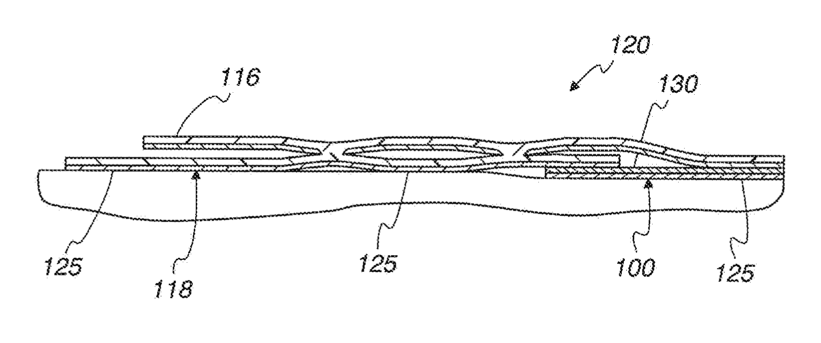
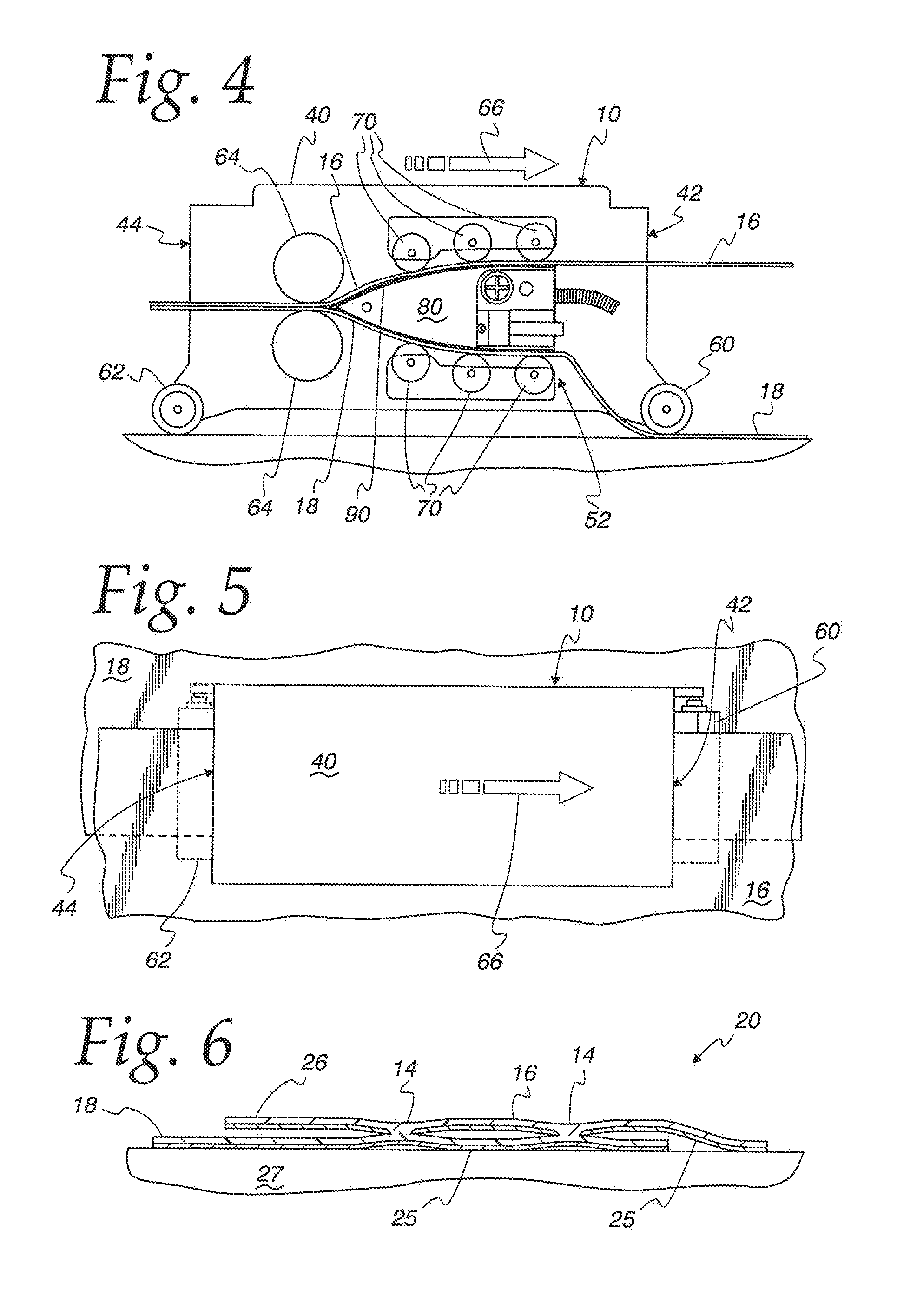
[0042]A heat welding apparatus 10 is disclosed in the Figures which may be used in accordance with the present invention to heat weld seams 14 between geomembrane panels 16, 18 (typically, rolls of plastic sheet) used to form a liner 20 for, for example, large containment areas, referred to herein generally as containment systems,

[0043]The panels 16, 18 are geomembranes formed of a suitable leak proof non-conductive material having a suitable integral conductive lower surface 25. The lower conductive surfaces of the individual panels 16, 18 may also be interconnected with a series of conductive geomembranes, wires, or other conductive media in a grid pattern, or other materials suitable for connecting individual panels. Moreover, in accordance with the present invention, the formed seams 14 between panels 16, 18 maybe be suitably tested for leaks even after covered with, for example, water and / or soil, allowing performance of a reliable leak location survey

[0044]In particular, in ac...


PUM

PropertyMeasurementUnit
diameteraaaaaaaaaa
diameteraaaaaaaaaa
non-conductive aaaaaaaaaa

Abstract

A geomembrane liner for a containment system including liner panels and connected by a seam at overlapped edges, with the top panel having a conductive lower surface which is non-conductive across the seam. Heat welding of the seams is accomplished by a welder having a heating unit with a projection which interrupts the conductive lower surface of the top panel before forming the seam. Such seams may be used separately or selectively with a lined containment system having a plurality of liner panels covering at least a portion of the containment system bottom. The liner panels have a conductive lower surface and overlap with adjacent panels, and conductive members underlie adjacent panels and contact the conductive lower surface of both adjacent panels to provide an electrical connection between the conductive lower surfaces of the adjacent panels.

Description

CROSS-REFERENCE TO RELATED APPLICATIONS[0001]Not Applicable.FEDERALLY SPONSORED RESEARCH OR DEVELOPMENT[0002]Not Applicable.MICROFICHE / COPYRIGHT REFERENCE[0003]Not Applicable.FIELD OF THE INVENTION[0004]The present invention relates to geomembrane liners, and more specifically to geomembrane liners facilitating detection of leaks therein.BACKGROUND OF THE INVENTION[0005]Lining systems for containment systems (e.g., systems which contain bodies of water such as ponds) and the like are used to provide an “impermeable” barrier between contaminants and the underlying ground. Generally, these liners are made of insulating material (such as high density polyethylene) which, even if thoroughly tested to be defect free when shipped, can be damaged during shipping and / or installation by, for example, heavy equipment, cutting tools, welding equipment, animals, and vandalism, necessitating that a final leak check be conducted after the liner is installed to locate leaks caused by any such dama...

Claims


Application Information

Patent Timeline
Patent Type & Authority Applications(United States)
IPC IPC(8): G01M3/40E02B3/12
CPCE02B3/121G01M3/40E02B5/02B29C65/20B29C66/1122B29C66/232B29C66/43B29C66/81417B29C66/81422B29C66/8324B29C66/86523E02B3/10B29C66/8362B29L2007/005B29C66/73141B29C66/73187E02D31/004B29C66/723B29C65/7439B29C66/02241B29C66/304B29C66/81427B29C66/8167B29C2793/0054B29C66/71B29C66/8221B29C65/8246B29C66/8432Y10T156/10Y10T156/1715B29C66/435B29K2023/065B29C66/843B29C65/02B29C65/7861B29C65/8276
Inventor YOUNGBLOOD, JR., JIMMIE GORDONGALLAGHER, DAVID JAMESZIMMEL, EDWARD JOSEPH
Owner GSE ENVIRONMENTAL
Why Eureka
Try Eureka