
Heat retention and distribution system for gas turbine engines

Inactive Publication Date: 2014-08-21
SIEMENS AG
View PDF3 Cites 17 Cited by
  • Summary
  • Abstract
  • Description
  • Claims
  • Application Information

AI Technical Summary

Benefits of technology

The invention is a gas turbine engine with a heat retention system that can maintain high temperatures in components during a shutdown to reduce maintenance consumption. The engine has a compressor section, combustor section, turbine section, and exhaust manifold. The recirculating flow of warmed air prevents flow of bleed air through certain sections during operation and reduces thermal mechanical fatigue of components. It also maintains a clearance between components and prevents damage to the engine during startup. The heat retention system is designed to extend the maintenance interval for the engine and improve overall efficiency.

Problems solved by technology

During operation of the engine, various components in the engine are subjected mechanical and thermal stresses that may reduce the mechanical integrity of the components over a period of engine operating time.

Method used


Image

  • Heat retention and distribution system for gas turbine engines
  • Heat retention and distribution system for gas turbine engines
  • Heat retention and distribution system for gas turbine engines

Examples


Embodiment Construction

[0028]In the following detailed description of the preferred embodiment, reference is made to the accompanying drawings that form a part hereof, and in which is shown by way of illustration, and not by way of limitation, a specific preferred embodiment in which the invention may be practiced. It is to be understood that other embodiments may be utilized and that changes may be made without departing from the spirit and scope of the present invention.

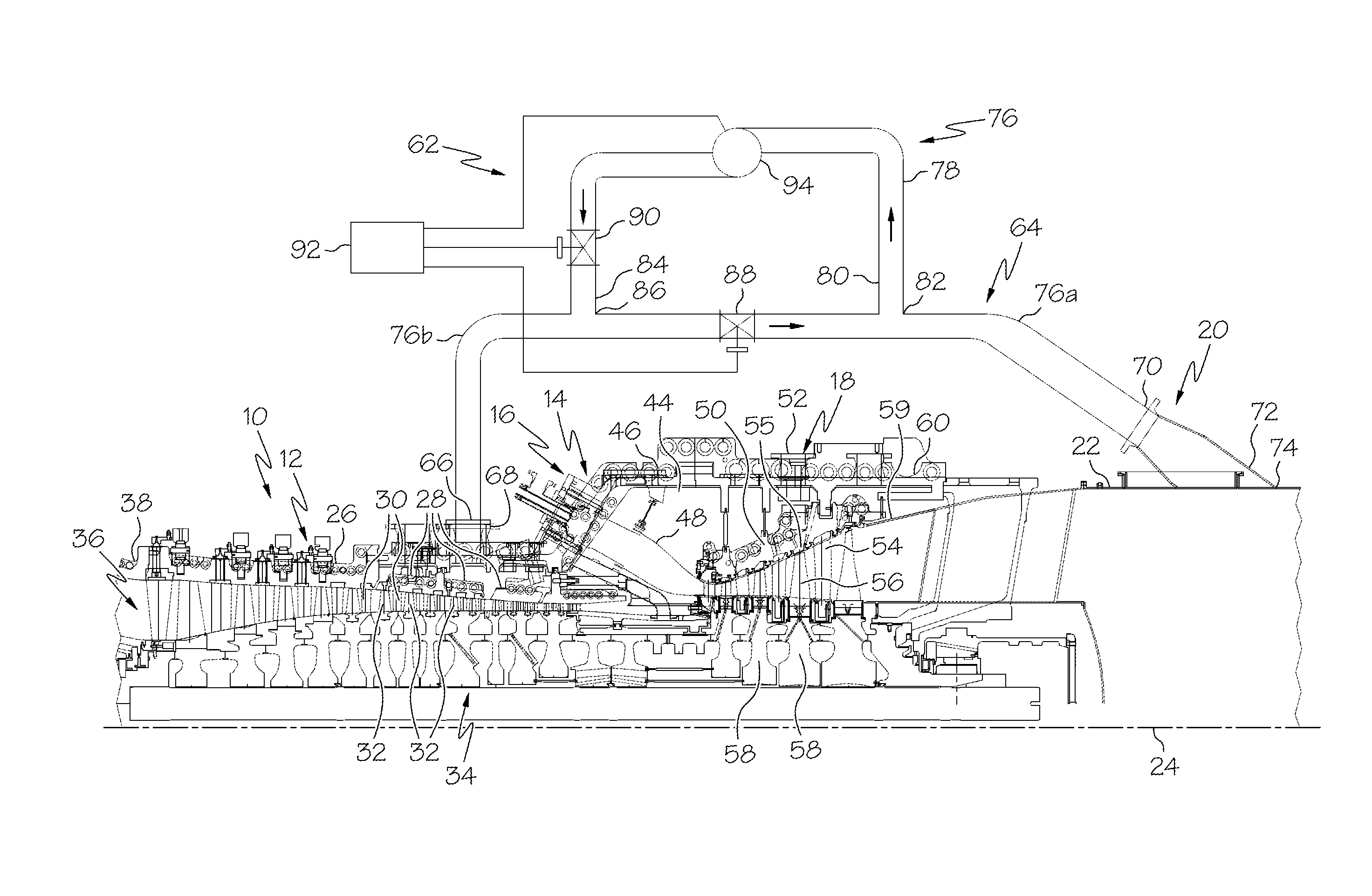
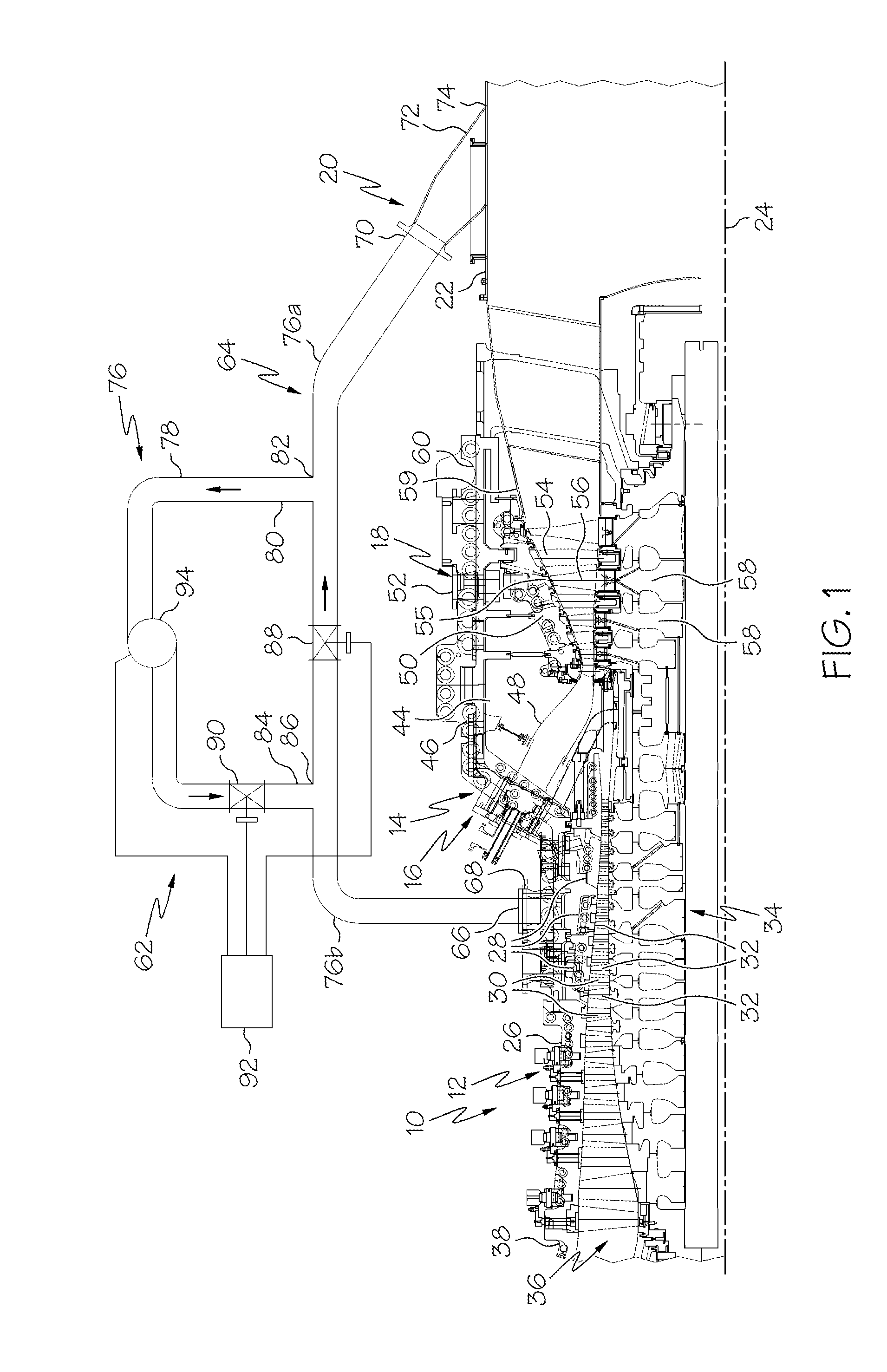
[0029]Referring to FIG. 1, a gas turbine engine 10 is shown illustrating aspects of the present invention. The engine includes a compressor section 12, a combustor section 14 including a plurality of combustors 16 (only one shown), and a turbine section 18. In addition, an exhaust manifold 20 comprising a manifold casing 22 is located downstream from the turbine section 18 for receiving expanded hot exhaust gases from the turbine section 18. It is noted that the engine 10 illustrated herein comprises an annular array of combustors 16 tha...


PUM


Abstract

A gas turbine engine including a compressor section, a combustor section, and a turbine section operating to produce a power output during a first mode of operation. A heat retention and distribution system is provided to the engine wherein the heat retention system operates in a second mode of operation, following a shutdown of the engine, to maintain an elevated temperature in components of each of the compressor section, the combustor section and the turbine section in order to effect (1) a reduction in an effective cyclic life consumption of the components and extend a maintenance interval associated with the effective cyclic life consumption, and (2) clearances by maintaining a higher vane carrier temperature with time during a non-power producing mode and more uniform temperature of most stationary components in the circumferential orientation.

Description

FIELD OF THE INVENTION[0001]The present invention relates to gas turbine engines and, more particularly, to a system for retaining heat in a gas turbine engine following shutdown of the engine.BACKGROUND OF THE INVENTION[0002]A gas turbine engine generally includes a compressor section, a combustor section, a turbine section and an exhaust section. In operation, the compressor section may induct ambient air and compress it. The compressed air from the compressor section enters one or more combustors in the combustor section. The compressed air is mixed with the fuel in the combustors, and the air-fuel mixture can be burned in the combustors to form a hot working gas. The hot working gas is routed to the turbine section where it is expanded through alternating rows of stationary airfoils and rotating airfoils and used to generate power that can drive a rotor. The expanded gas exiting the turbine section may then be exhausted from the engine via the exhaust section.[0003]During operat...

Claims


Application Information

Patent Timeline
IPC IPC(8): F02C7/00
CPCF02C7/00F01D5/08F01D11/24F01D25/10F05D2260/20F05D2260/85F02C7/08
Inventor LIGHT, KEVIN M.ROSS, CHRISTOPHER W.
Owner SIEMENS AG
Learn More