Methods and Systems of Constructing a Multi Rotor Aircraft Fuselage

a multi-rotor aircraft and fuselage technology, applied in the field of aviation, can solve the problems of significant frame distortion, constant need of maintenance, and relatively heavy fuselage frames, and achieve the effects of less external force load, greater efficiency, and more payload

Inactive Publication Date: 2014-08-21
HEADRICK SEAN
View PDF20 Cites 57 Cited by
  • Summary
  • Abstract
  • Description
  • Claims
  • Application Information

AI Technical Summary

Benefits of technology

[0015]Disclosed embodiments include new means and methods of thin shell construction which combine motors, electronic assemblies and other components into a single thermoformed polymer shell assembly. This type of construction allows for external forces to be dispersed over the entire “skin” or outer surface of the shell as opposed to concentrating those forces on a few small fasteners as found in the prior art. In the disclosed embodiments, fasteners are of similar material to the shell. The similarity of material assists in dissipating the load of external forces. In strong contrast, the prior art's use of dissimilar materials between fasteners and fuselage parts causes dangerous distortion in the weaker material.
[0016]Disclosed metho...

Problems solved by technology

A noted shortfall in the related art is that fuselage frames are relatively heavy and fragile and are in constant need of maintenance that includes tightening and alignment procedures.
In the event of crash, sudden change in speed or exposure to high external forces, the cumulative effect of many fastener locations can result in significant frame distortion.
In prior art systems, some level of this distortion persists even after the force has subsided.
This means that any force applied to the end (distal end) of the motor mount arm is mul...

Method used


Image

  • Methods and Systems of Constructing a Multi Rotor Aircraft Fuselage
  • Methods and Systems of Constructing a Multi Rotor Aircraft Fuselage
  • Methods and Systems of Constructing a Multi Rotor Aircraft Fuselage

Examples


Embodiment Construction

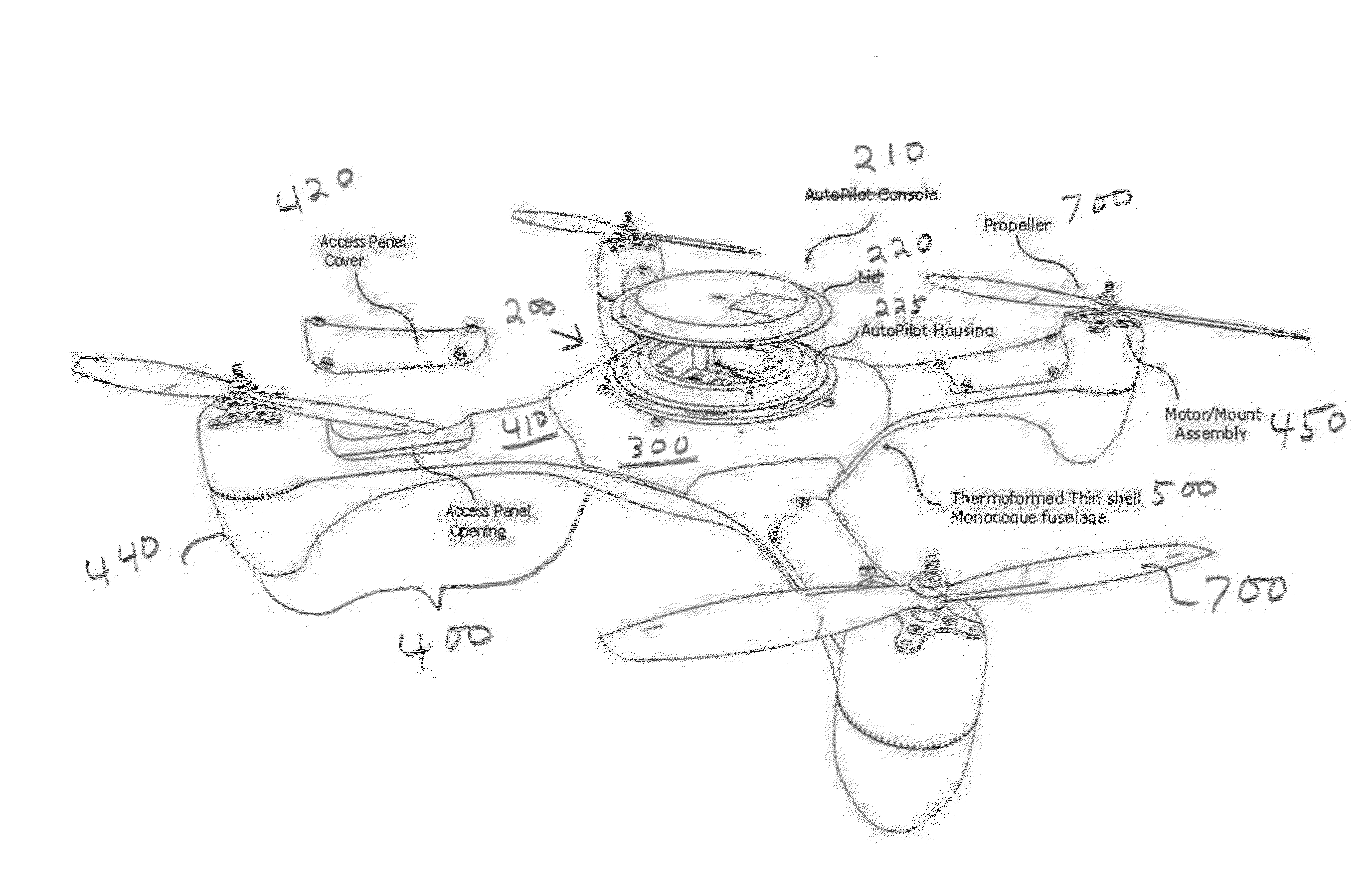
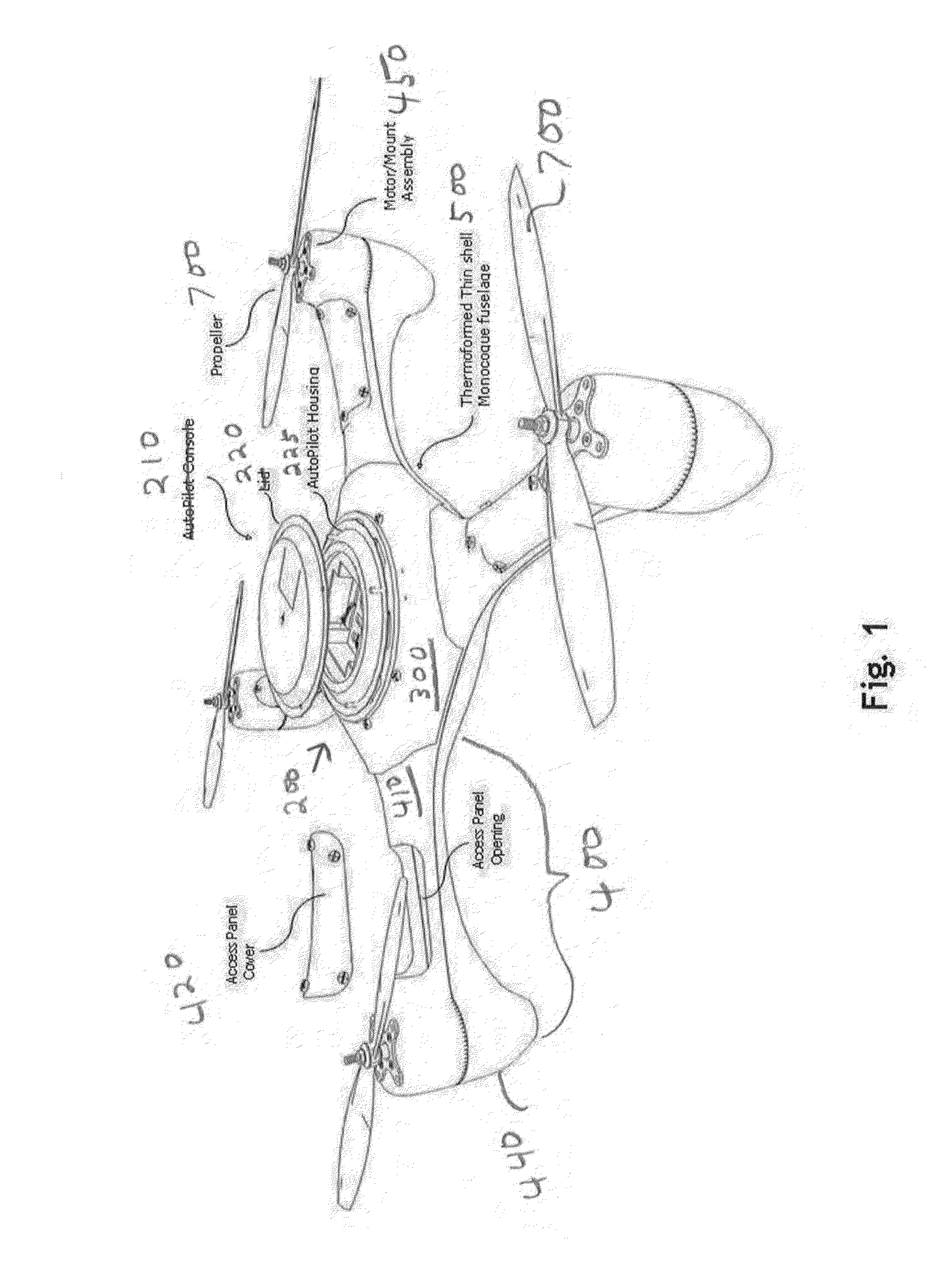
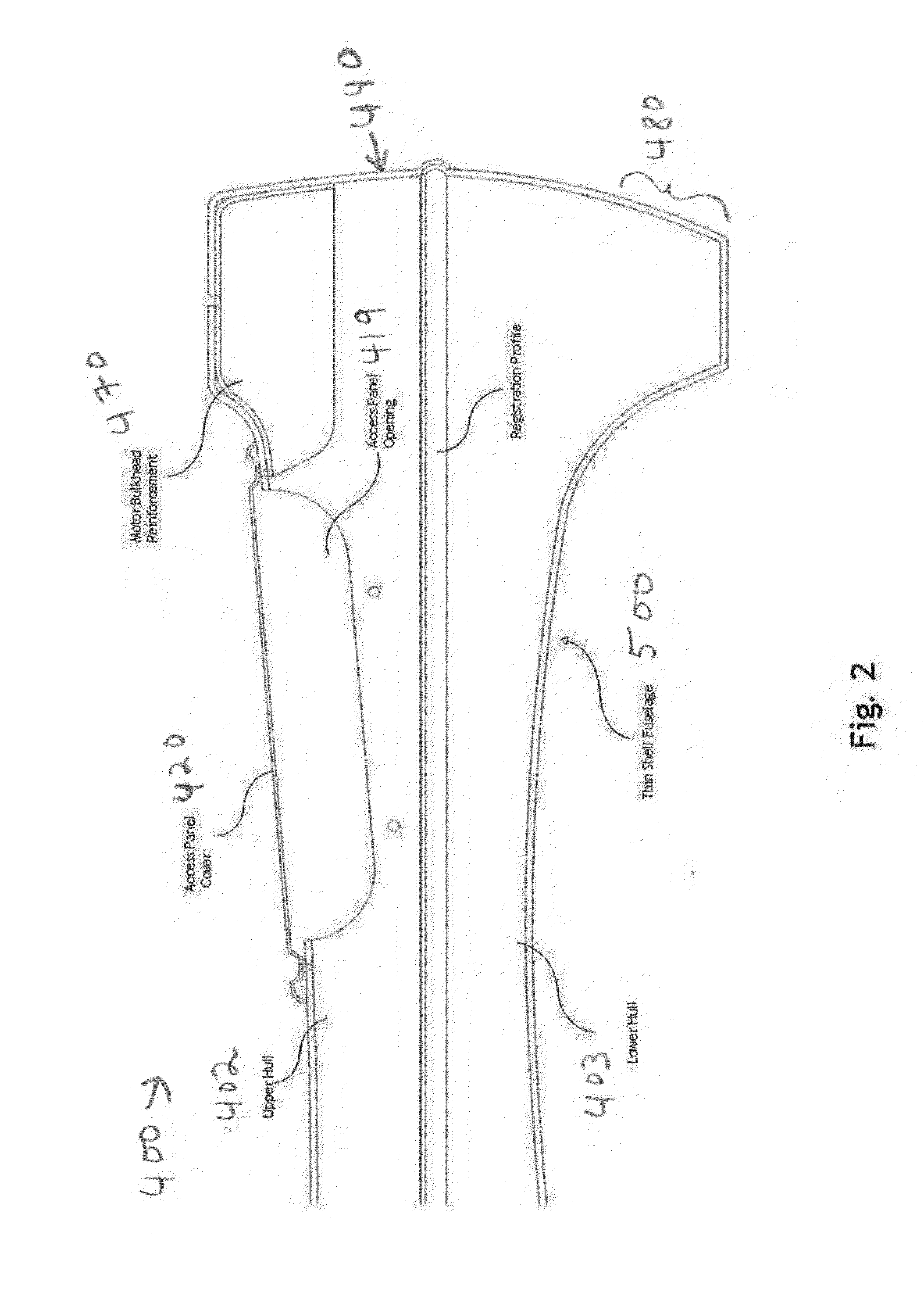
[0067]The following detailed description is directed to certain specific embodiments of the invention. However, the invention can be embodied in a multitude of different ways as defined and covered by the claims and their equivalents. In this description, reference is made to the drawings wherein like parts are designated with like numerals throughout.

[0068]Unless otherwise noted in this specification or in the claims, all of the terms used in the specification and the claims will have the meanings normally ascribed to these terms by workers in the art.

[0069]Unless the context clearly requires otherwise, throughout the description and the claims, the words “comprise,”“comprising” and the like are to be construed in an inclusive sense as opposed to an exclusive or exhaustive sense; that is to say, in a sense of “including, but not limited to.” Words using the singular or plural number also include the plural or singular number, respectively. Additionally, the words “herein,”“above,”“...


PUM


Abstract

A lower hull 403 and an upper hull 402 may form a multi rotor aircraft fuselage system comprising a comprising a thermoformed thin shell monocoque fuselage 500, center console assembly 200, the center console assembly comprising a center console cover 210, an auto pilot housing cover 220 and an auto pilot housing 225. A center fuselage area 300 contains the center console assembly 200. The center fuselage area is part of a plurality of arm assemblies 400. Each arm assembly may comprise a distal end 440 and a proximal end 410, an access panel cover 420 which may expose a access panel opening 419. An access panel opening 419 may lead to an arm void area 430, with the arm void area 430 further defined by the interior sections of the thin shell fuselage 500.

Description

CROSS-REFERENCE TO RELATED APPLICATIONS[0001]This is a utility application based upon U.S. patent application Ser. No. 61 / 709,269 filed on Oct. 3, 2012. This related application is incorporated herein by reference and made a part of this application. If any conflict arises between the disclosure of the invention in this utility application and that in the related provisional application, the disclosure in this utility application shall govern. Moreover, the inventor(s) incorporate herein by reference any and all patents, patent applications, and other documents hard copy or electronic, cited or referred to in this application.COPYRIGHT AND TRADEMARK NOTICE[0002]This application includes material which is subject or may be subject to copyright and / or trademark protection. The copyright and trademark owner(s) has no objection to the facsimile reproduction by any of the patent disclosure, as it appears in the Patent and Trademark Office files or records, but otherwise reserves all copy...

Claims


Application Information

Patent Timeline
IPC IPC(8): B64C27/08B64D27/00B64C1/00
CPCB64C27/08B64D27/00B64C1/00B64C1/36B64C39/024B64U10/13B64U30/20
Inventor HEADRICK, SEAN
Owner HEADRICK SEAN
Why Eureka
Try Eureka