Leading edge rib assembly
- Summary
- Abstract
- Description
- Claims
- Application Information
AI Technical Summary
Benefits of technology
Problems solved by technology
Method used
Image

Examples
Embodiment Construction
)
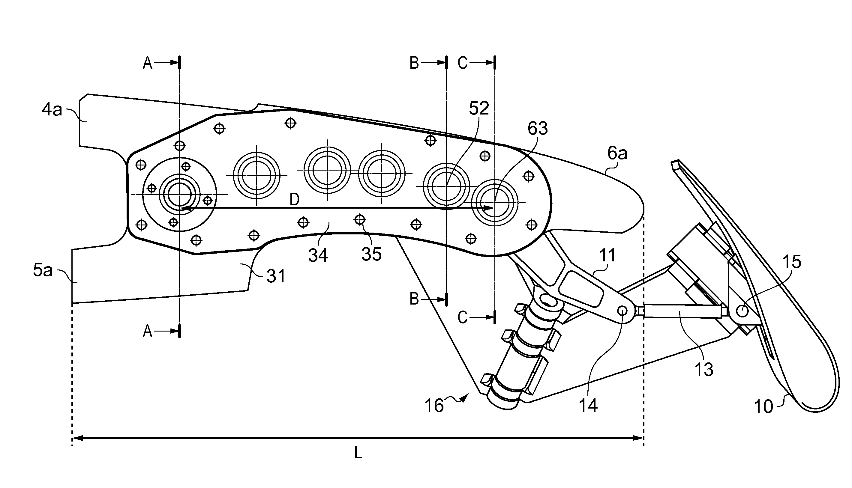
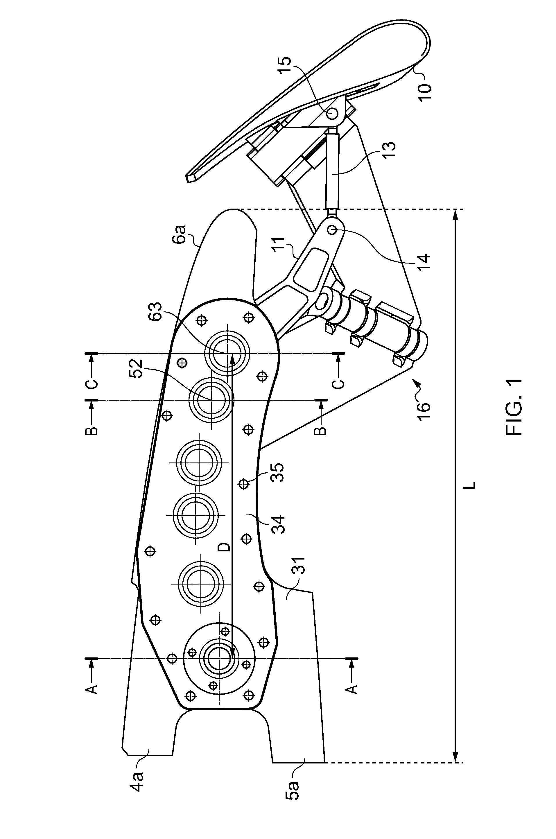
[0025]FIGS. 8-10 show the leading edge of an aircraft wing. The wing has a main element with a rear spar (not shown), a forward spar 1, and an upper skin 2 and lower skin 3 attached to (and extending between) the spars. The forward spar 1 supports a series of leading edge ribs which extend forward of the spar, one of the leading edge ribs being shown in FIGS. 9 and 10 and five of the leading edge ribs being shown in FIG. 8. Each leading edge rib has a proximal end with a pair of legs 4, 5 which are bolted to the spar 1, and a distal end 6 at which it supports a D-nose leading edge skin panel 7. The panel 7 is bolted to the rib through bolt holes 8 shown in FIG. 8.
[0026]Note that FIG. 9 illustrates the upper skin 2 and leading edge skin panel 7 as a single continuous part, but in practice a joint (not shown) is formed between the upper skin 2 and the leading edge skin panel 7.
[0027]A Krueger flap 10 is stowed on an under surface of the main wing element so that it lies flush with th...
PUM
 Abstract
Description
Claims
Application Information
 - R&D Engineer
- R&D Manager
- IP Professional
- Industry Leading Data Capabilities
- Powerful AI technology
- Patent DNA Extraction
Browse by: Latest US Patents, China's latest patents, Technical Efficacy Thesaurus, Application Domain, Technology Topic.
© 2024 PatSnap. All rights reserved.Legal|Privacy policy|Modern Slavery Act Transparency Statement|Sitemap