Compact fiber-based scanning laser detection and ranging system

a fiber-based scanning laser and optical fiber technology, applied in the field of optical fiber-based scanning laser detection, can solve the problems of limited scanning speed and angle, high cost of scanning techniques, and large volume and weight, and achieve the effect of sufficient spatial resolution

Inactive Publication Date: 2014-08-21
UNITED STATES OF AMERICA THE AS REPRESENTED BY THE SEC OF THE ARMY
View PDF7 Cites 56 Cited by
  • Summary
  • Abstract
  • Description
  • Claims
  • Application Information

AI Technical Summary

Problems solved by technology

These scanning techniques suffer from high cost, large volume and weight, and / or limited scanning speed and angle.

Method used


Image

  • Compact fiber-based scanning laser detection and ranging system
  • Compact fiber-based scanning laser detection and ranging system
  • Compact fiber-based scanning laser detection and ranging system

Examples


Embodiment Construction

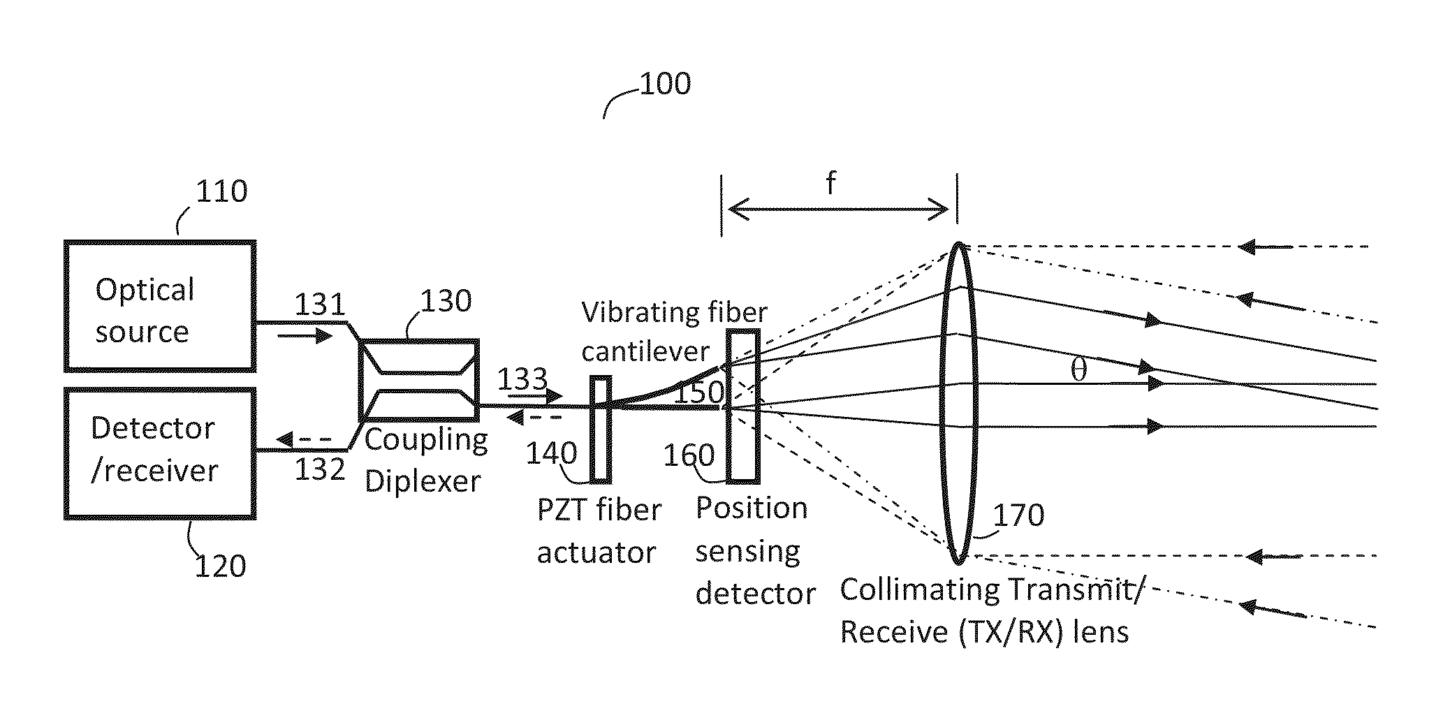
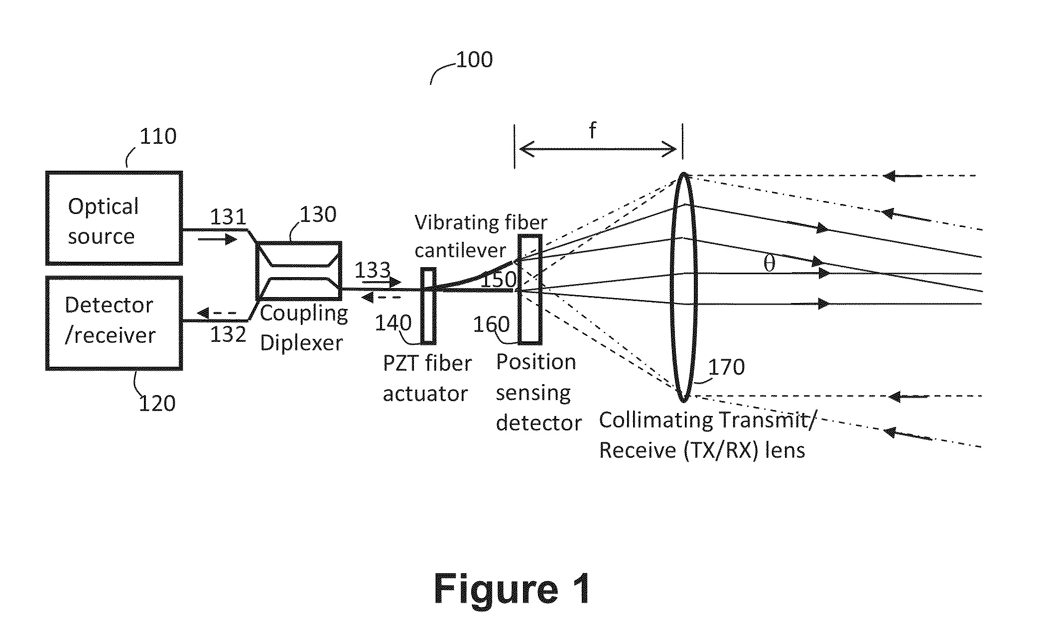
[0016]An exemplary LADAR system 100, shown in FIG. 1, is based on the following functionalities: 1. Fiber-based monostatic transmitter / receiver, 2. Fiber beam scanner based on a laterally vibrating fiber cantilever (e.g., 140), 3. Position sensor (e.g., 160) to monitor the transmitted beam position and hence propagation angle of the transmitted collimated optical beam. These components and their interaction are detailed below.

[0017]Exemplary components of such an LADAR system 100 are an optical source 110, e.g., an eye-safe 1550 nm pulsed fiber laser or master oscillator-power-amplifier (MOPA), and a photo detector 120 for converting the received optical LADAR pulses into electrical signals that are processed by the receiver electronics to extract range information. The all-fiber MOPA incorporates a fiber laser that amplifies an optical seed pulse from a semiconductor laser diode, of a fiber-coupled type that is readily available as standard fiber telecommunications products. The pu...


PUM


Abstract

A system for short-range laser detection and ranging of targets can provides rapid three-dimensional, e.g., angle, angle, range, scans over a wide field-of-view. Except for the final transmit / receive lens, the disclosed LADAR system can be implemented in an all-fiber configuration. Such system is compact, low cost, robust to misalignment, and lends itself to eye-safe operation by making use of available pulsed 1550 nm fiber lasers and amplifier sources. The disclosed LADAR system incorporates many novel features that provide significant advantages compared to current LADAR systems. The disclosed system uses a monostatic fiber-based transmitter / receiver, a fiber beam scanner based on a laterally vibrating fiber, and a position sensor to monitor the transmitted beam position.

Description

GOVERNMENT INTEREST[0001]The invention described herein may be manufactured, used, sold, imported, and / or licensed by or for the Government of the United States of America.FIELD OF THE INVENTION[0002]This invention relates in general to laser detection and ranging, and more particularly, to fiber-based scanning laser detection.BACKGROUND OF THE INVENTION[0003]A typical method of operation for laser detection and ranging (LADAR) is to emit a short (˜ns) optical pulse in a narrow beam and detect its reflected return from a target. The time delay between emission and detection provides the range to the target, and knowledge of the transmitted beam angle / direction provides target bearing information. The transmitted beam is collimated to provide low divergence to the target. In general, the target will reflectively scatter the incident beam into a large solid angle, so the amount of reflected power detected at the LADAR system will be proportional to the area of the receiver aperture. I...

Claims


Application Information

Patent Timeline
Patent Type & Authority Applications(United States)
IPC IPC(8): G01S17/10G01S7/486G01S17/89
CPCG01S17/10G01S17/89G01S7/4812G01S7/4817G01S7/4818G01S7/486
Inventor CHINN, STEPHENGOLDBERG, LEW
Owner UNITED STATES OF AMERICA THE AS REPRESENTED BY THE SEC OF THE ARMY
Why Eureka
Try Eureka