Shield structure for electron beam sterilization equipment

a shielding structure and shielding technology, applied in the direction of material analysis using wave/particle radiation, instruments, transportation and packaging, etc., can solve the problems of continuous radiation, serious shielding or attenuation of electron beams (x-rays) leaking from the entrance or exit of the container formed on the shield chamber, etc., to effectively attenuate the leakage of electron beams upstream, increase the number of electron beam reflections, and reduce the effect of radiation

Inactive Publication Date: 2014-08-21
HITACHI ZOSEN CORP
View PDF13 Cites 14 Cited by
  • Summary
  • Abstract
  • Description
  • Claims
  • Application Information

AI Technical Summary

Benefits of technology

[0020]According to the first aspect of the present invention, the internal circumferential shield is mounted along the internal circumference of the revolving channel in the sterilization zone. Thus, the number of reflections of electron beams is increased between the shield chambers and the internal circumferential shields, achieving effective attenuation. Moreover, electron beams (X-rays) leaking from the container entrance and the container exit of the shield chamber in the sterilization zone can be effectively blocked by the internal circumferential shields disposed in a trap zone. This can effectively attenuate electron beams (X-rays) leaking upstream and downstream.
[0021]In condition (I), a sufficient transport distance and time is necessary for the insertion of the electron beam irradiation nozzle and radiation. Thus, the revolving channel needs to be increased in length and diameter. As the revolving channel of the trap zone disposed at the container exit increases in diameter, the diameter of the revolving channel in the inner-surface sterilization zone is limited. Thus, the revolving channel cannot have a large diameter in the trap zone. This necessarily tends to increase an electron beam (X-ray) dose leaking from the container exit of the inner-surface sterilization zone to the shield chamber upstream of the trap zone. In order to address this problem, the outer diameter of the internal circumferential shield of the downstream revolving channel is set larger than that of the internal circumferential shield near the container exit. This can effectively block and reduce a dose of radiation leaking downstream from the upstream shield chamber.
[0022]In condition (II), the internal circumferential shield of the revolving channel downstream of the entrance trap zone connected to the container entrance of the outer-surface sterilization zone has a larger outer diameter than the internal circumferential shield of the revolving channel upstream of the outer-surface sterilization zone. This can effectively block and reduce an electron beam (X-ray) dose leaking from the inner-surface sterilization zone and the outer-surface sterilization zone through the container entrance.
[0023]According to the second aspect of the present invention, the outer diameter of the internal circumferential shield of the downstream revolving channel is 1.3 to 2.5 times larger than that of the internal circumferential shield near the container exit. Thus, the enhanced effect of blocking and reducing a dose of radiation leaking downstream from the upstream shield chamber can be obtained without excessively increasing the size of a facility.
[0024]According to the third aspect of the present invention, the internal circumferential shield of the revolving channel downstream of the entrance trap zone connected to the container entrance of the outer-surface sterilization zone has an outer diameter 1.3 to 2.5 times larger than the outer diameter of the internal circumferential shield of the revolving channel upstream of the outer-surface sterilization zone. This can obtain the enhanced effect of blocking and reducing an electron beam (X-ray) dose leaking from the inner-surface sterilization zone and the outer-surface sterilization zone through the container entrance without excessively increasing the size of a facility.
[0025]According to the fourth aspect of the present invention, the trap wall is provided in the shield chamber upstream of the exit trap zone to form the attenuating chamber. Thus, electron beams (X-rays) leaking from the container exit of the inner-surface sterilization zone can be guided into the attenuating chamber by the trap wall. This can effectively reflect and attenuate electron beams (X-rays) in the attenuating chamber.

Problems solved by technology

In this case, an electron beam generator cannot turn on or off electron radiation because a high voltage is supplied, leading to continuous radiation.
Thus, electron beams (X-rays) leaking from the entrance or exit of the container formed on the shield chamber may be seriously shielded or attenuated.

Method used


Image

  • Shield structure for electron beam sterilization equipment
  • Shield structure for electron beam sterilization equipment
  • Shield structure for electron beam sterilization equipment

Examples


first embodiment

[0053]A first embodiment of electron beam sterilization equipment for containers including a shield structure according to the present invention will be described below with reference to the accompanying drawings.

[0054][Outline of Electron Beam Sterilization Equipment]

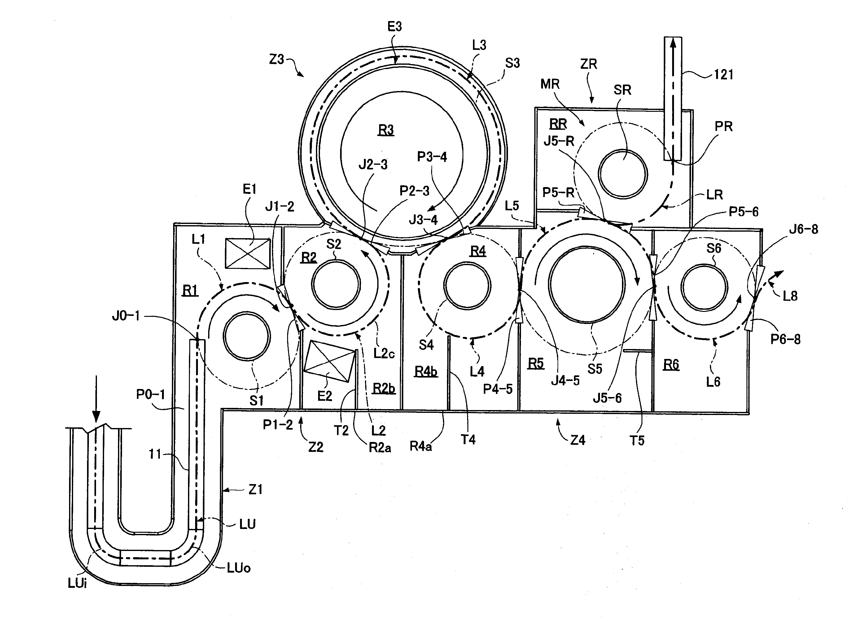
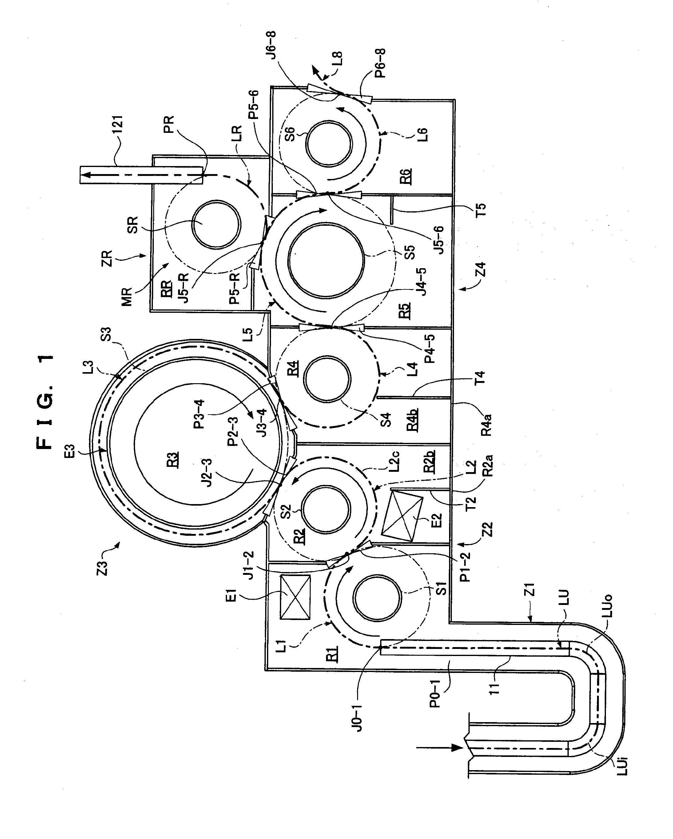
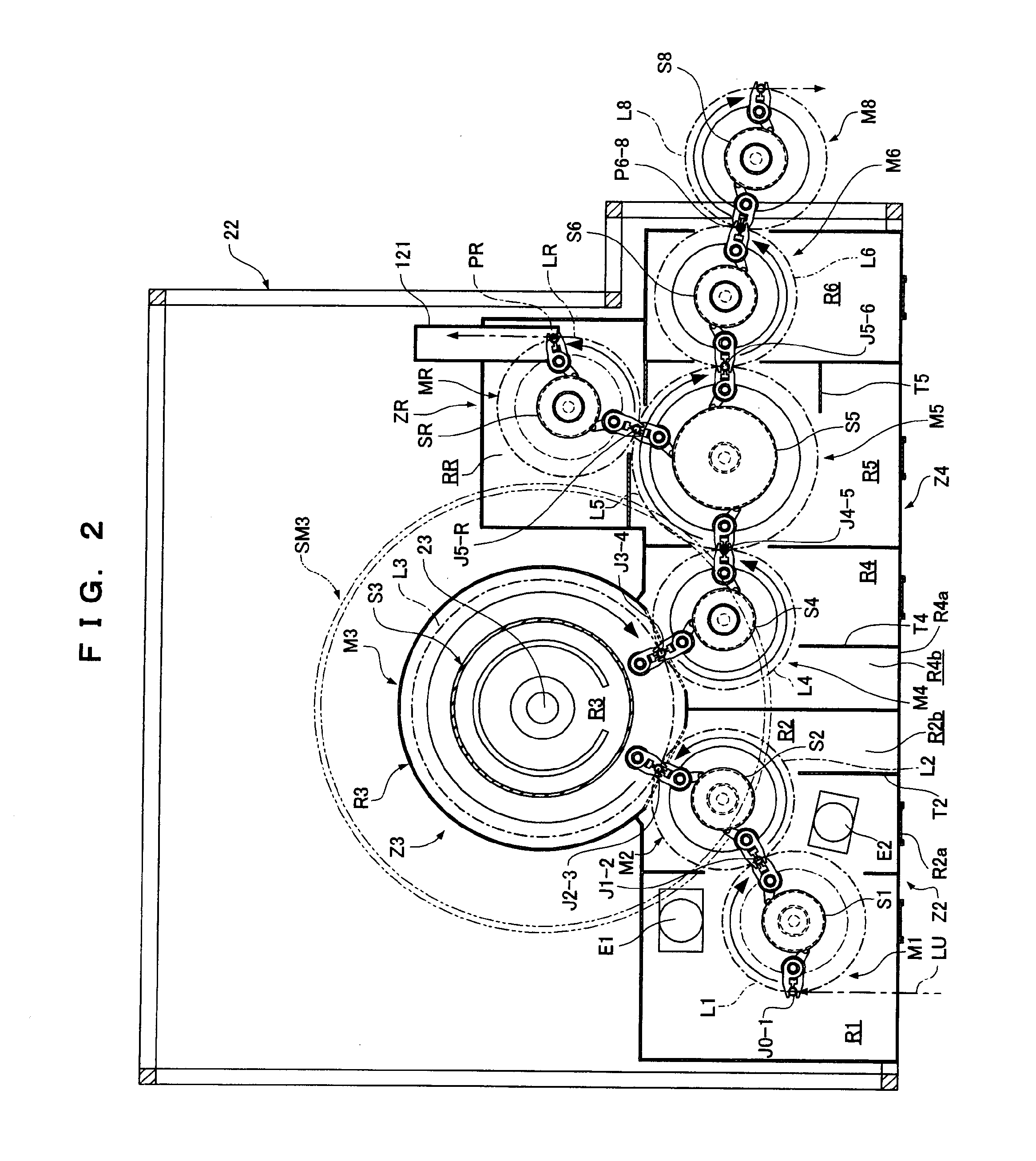
[0055]As shown in FIGS. 1 to 3, electron beam sterilization equipment includes an entrance trap zone Z1, an outer-surface sterilization zone Z2, an inner-surface sterilization zone Z3, and an exit trap zone Z4. The entrance trap zone Z1 includes a U-shaped feed channel LU. The outer-surface sterilization zone Z2, the inner-surface sterilization zone Z3, and the exit trap zone Z4 are configured such that first to sixth revolving channels L1 to L6 for transporting containers B by means of first to sixth revolving conveyors M1 to M6 are connected in series. Furthermore, on the back of the exit trap zone Z4, a reject zone ZR is provided to transport insufficiently sterilized ones of the containers B along a reject revolvin...

second embodiment

[0129]Referring to FIGS. 15, 16A and 16B, a second embodiment of electron beam sterilization equipment according to the present invention will be described below. In the second embodiment, an entrance trap zone Z1 includes a plurality of circular paths LT1 and LT2.

[0130]In the entrance trap zone Z1, the first trap revolving channel LT1 and the second trap revolving channel LT2 are connected in series between a first revolving channel L1 and a carry-in revolving channel LS formed by a carry-in revolving conveyor M0. Moreover, a first trap revolving conveyor MT1 forming the first trap revolving channel LT1 and a second trap revolving conveyor MT2 forming the second trap revolving channel LT2 are respectively stored in a first trap shield chamber RT1 and a second trap shield chamber RT2 that are formed by metallic shield walls. In the carry-in revolving conveyor M0 and the first and second trap revolving conveyors MT1 and MT2, a carry-in part internal circumferential shield wall S0 and...


PUM

PropertyMeasurementUnit
circumferenceaaaaaaaaaa
outer diameteraaaaaaaaaa
speedaaaaaaaaaa

Abstract

A shield structure for electron beam sterilization equipment. The shield structure satisfies at least one of the following conditions: (I) an outer diameter D4 of an internal circumferential shield S4 is larger than an outer diameter D5 of an internal circumferential shield S5, and (II) an internal circumferential shield ST2 of a circular path LT2 downstream of an entrance trap zone Z1 connected to an outer-surface sterilization zone Z2 has an outer diameter DT2 that is larger than an outer diameter D1 of an internal circumferential shield S1 of a circular path L1 upstream of the outer-surface sterilization zone Z2.

Description

TECHNICAL FIELD[0001]The present invention relates to a shield structure for electron beam sterilization equipment that sterilizes containers and instruments for foods, chemical solutions, and so on by electron radiation.BACKGROUND ART[0002]When electron beams (cathode rays) emitted for sterilizing cellular microorganisms collide with metallic shields (containing lead) disposed as shields, the electron beams are attenuated and then are reflected and diffracted as X-rays in a widely diffused state. For example, if electron beams collide with the shield three or four times, although depending on the intensity thereof, X-rays can be attenuated to a degree of intensity that does not affect a human body.[0003]For example, if an electron beam irradiation nozzle is inserted into the inlet of a container to sterilize the inner surface of the container, electron beams are emitted from the entire periphery of the electron beam irradiation nozzle. If a revolving transport device that is a rota...

Claims


Application Information

Patent Timeline
Patent Type & Authority Applications(United States)
IPC IPC(8): A61L2/00
CPCA61L2/00A61L2/087B65B55/08B65G47/847B01J19/085
Inventor YOKOBAYASHI, TAKAYASUOGAWA, SATOSHIHOSOKAWA, TORU
Owner HITACHI ZOSEN CORP
Why Eureka
Try Eureka