
Evaluation Circuit for an Optoelectronic Detector and Method for Recording Fluorescence Events

Active Publication Date: 2014-08-21
CARL ZEISS MICROSCOPY GMBH
View PDF5 Cites 3 Cited by
  • Summary
  • Abstract
  • Description
  • Claims
  • Application Information

AI Technical Summary

Benefits of technology

The invention aims to enhance the evaluation circuit of this type to achieve highly sensitive detection in a cost-effective manner.

Problems solved by technology

Scattered light in any form is undesirable for high-sensitivity fluorescence measurement regardless of whether it is direct excitation light arriving in the detection channel (in spite of spectral separation), diffuse scattered light of optical components, excitation light reflected at surfaces, or light scattered from the sample (particularly Rayleigh scattered light and Raman scattered light).
Raman scattering takes place at the solvent contained in the samples to be examined and cannot be prevented in any excited sample.
In aqueous biological samples, the scattered light occurring through Raman scattering is typically spectrally located in the wavelength range of the fluorescence emission and presents an obstacle to precise measurements which cannot be overcome by commonly used spectral filtration.
Conversely, fluorescence interferes with the measurement of a Raman spectrum which is typically carried out for determining the molecules present in the sample because the fluorescence cannot be spectrally filtered from the Raman spectrum.
However, the evaluation circuit described therein requires a synchronization of the analog-to-digital converter with the light pulses so that either only fluorescent light can be captured or it is impossible to distinguish between fluorescent light and scattered light, particularly not retrospectively.

Method used


Image

  • Evaluation Circuit for an Optoelectronic Detector and Method for Recording Fluorescence Events
  • Evaluation Circuit for an Optoelectronic Detector and Method for Recording Fluorescence Events
  • Evaluation Circuit for an Optoelectronic Detector and Method for Recording Fluorescence Events

Examples


Embodiment Construction

[0040]It is to be understood that the figures and descriptions of the present invention have been simplified to illustrate elements that are relevant for a clear understanding of the present invention, while eliminating, for purposes of clarity, many other elements which are conventional in this art. Those of ordinary skill in the art will recognize that other elements are desirable for implementing the present invention. However, because such elements are well known in the art, and because they do not facilitate a better understanding of the present invention, a discussion of such elements is not provided herein.

[0041]The present invention will now be described in detail on the basis of exemplary embodiments.

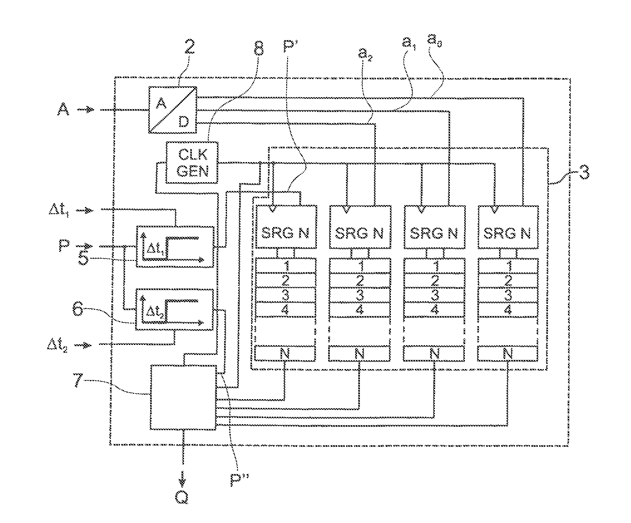
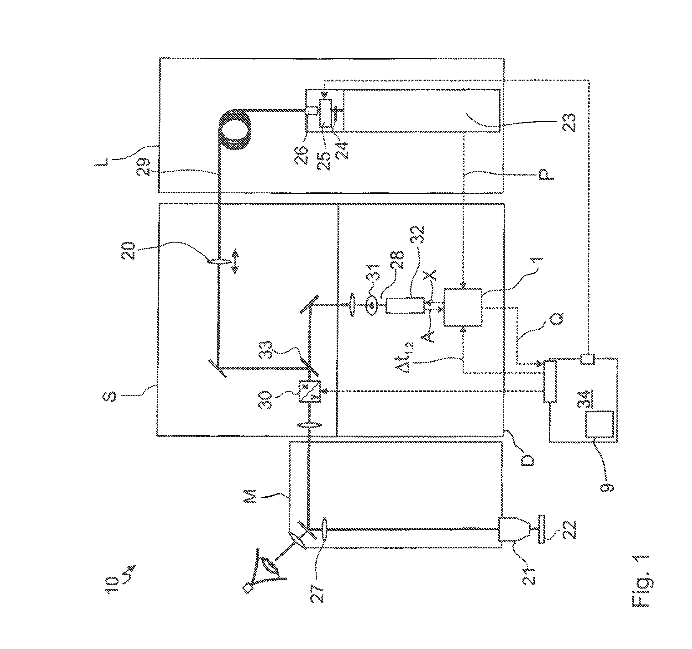
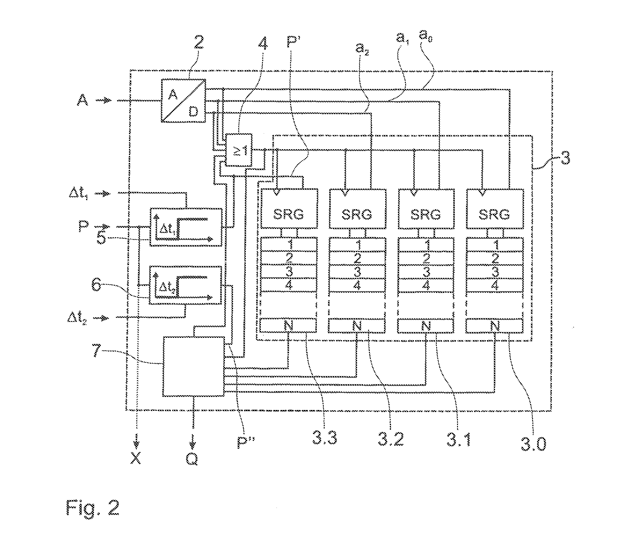
[0042]FIG. 1 is a schematic depiction of an evaluation circuit 1 in a laser scanning microscope 10 (LSM). The LSM 10 is constructed modularly from an illumination module L with a pulsed laser as tight source 23, a scanning module S, a detection module D and microscope unit M wi...


PUM


Abstract

An improved evaluation circuit which allows high sensitivity in an economical manner. For this purpose, a shift register having at least one data input, a clock input, a plurality of register stages and at least one data output is provided, wherein the output of the analog-to-digital converter is connected to the data input of the shift register. With a shift register, fluorescent light and scattered light can be temporally distinguished in an economical manner.

Description

[0001]The present application claims priority from PCT Patent Application No. PCT / EP2012 / 003939 filed on Sep. 20, 2012, which claims priority from German Patent Application No. DE 10 2011 114 874.8 filed on Sep. 30, 2011, the disclosures of which are incorporated herein by reference in their entirety.FIELD OF THE INVENTION[0002]The invention is directed to an evaluation circuit for evaluating the electric signals of an optoelectronic detector, particularly during the capture of fluorescence events during excitation by means of light pulses, comprising an analog-to-digital converter (ADC) with an input for connecting to an output of the detector and with an output for outputting a digital value, and to a method for recording fluorescence events by means of an optoelectronic detector, particularly in a microscope, wherein light pulses are radiated onto a sample by means of a light source and light from the sample is captured by means of the detector and is converted into an electric s...

Claims


Application Information

Patent Timeline
IPC IPC(8): G01N21/64
CPCG01N21/64G01J3/2889G01N21/6408G02B21/0076G01N21/6458G02B21/0084G01J1/44G01J3/44
Inventor MOHLER, GUNTERSCHMIDT, DIETMARHOLUB, OLIVERHAUSCHILD, ROBERT
Owner CARL ZEISS MICROSCOPY GMBH
Learn More