Interior magnet linear induction motor
a technology of linear induction motor and inner magnet, which is applied in the direction of dynamo-electric machines, electrical apparatus, propulsion systems, etc., can solve the problems of limited application range high manufacturing cost, and large number of magnets used, so as to increase thrust and increase thrust per unit facing area, the effect of widening the range of application of induction type motors
- Summary
- Abstract
- Description
- Claims
- Application Information
AI Technical Summary
Benefits of technology
Problems solved by technology
Method used
Image
Examples
first embodiment
[Configuration of Interior Magnet Linear Induction Motor]
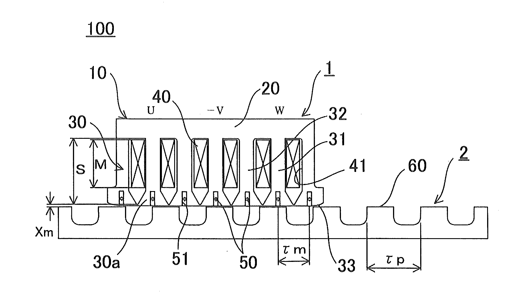
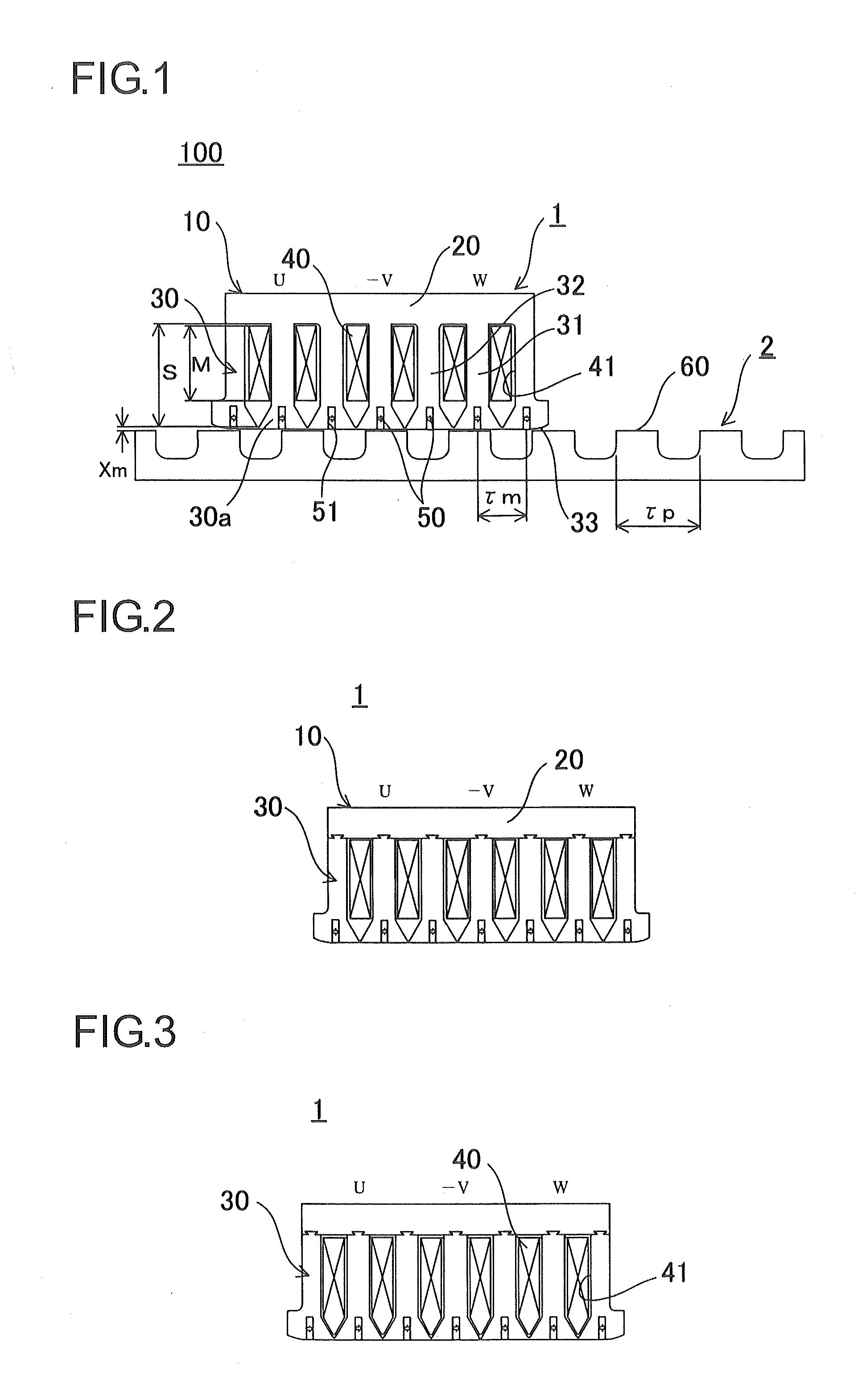
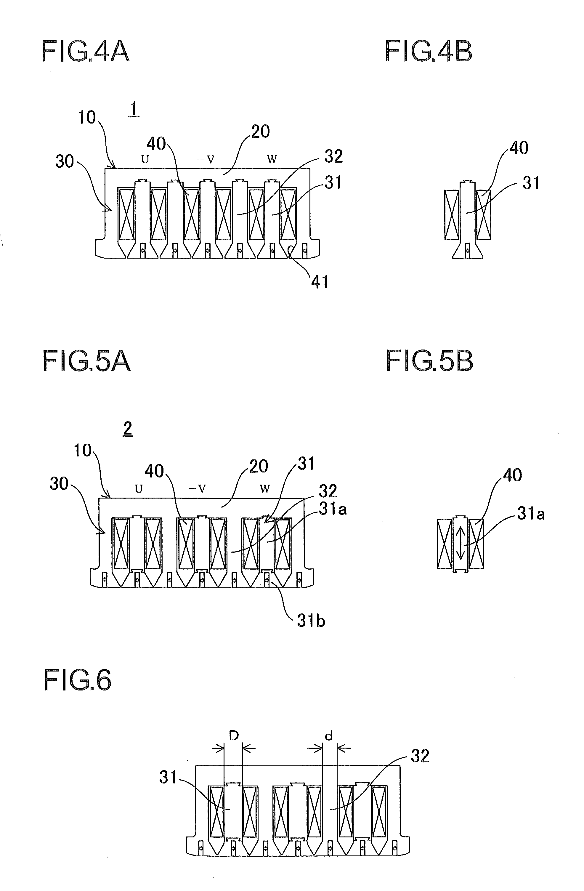
[0052]First, with reference to FIGS. 1 to 10, the configuration of an interior magnet linear induction motor of the first embodiment will be described. FIG. 1 is a schematic plan view of an interior magnet linear induction motor of the first embodiment.
[0053]FIG. 1 illustrates a basic embodiment of the first embodiment, and FIGS. 2 to 10 illustrate modified examples of the basic embodiment. The first embodiment will be described on the basis of the basic embodiment of FIG. 1 and, as necessary, the modified examples will be described with reference to FIGS. 2 to 10.
[0054]As illustrated in FIG. 1, an interior magnet linear induction motor 100 of the first embodiment includes an armature 1 and a line of inductor teeth 2 that faces the armature 1.
[0055]The armature 1 includes an armature core 10, coils 40, and permanent magnets 50. The armature core 10 includes a yoke 20 and a plurality of teeth 30. The armature core 10 may be a u...
second embodiment
[0115]Next, with reference to FIGS. 14 to 19, an interior magnet linear induction motor 200 of a second embodiment will be described. FIG. 14 is a schematic plan view of the interior magnet linear induction motor 200 of the second embodiment. FIG. 15 is a schematic plan view of a main part of FIG. 14. Note that elements that are the same as those of the interior magnet linear induction motor 100 of the first embodiment are denoted by the same reference numerals and description thereof will be omitted.
[0116]As illustrated in FIG. 14, the interior magnet linear induction motor 200 of the second embodiment differs from the interior magnet linear induction motor 100 of the first embodiment in terms of the number of the permanent magnets 50 and magnetization arrangement.
[0117]As illustrated in FIGS. 14 and 15, in the second embodiment, except for the teeth 30 at both ends, two permanent magnets 50 are arranged at each of the end portions 30a of the teeth 30. The permanent magnets 50 are ...
third embodiment
[0130]Next, with reference to FIGS. 20 to 23, an interior magnet linear induction motor 300 of a third embodiment will be described. FIG. 20 is a schematic plan view of the interior magnet linear induction motor 300 of the third embodiment. Note that elements that are the same as those of the interior magnet linear induction motor 100 of the first embodiment are denoted by the same reference numerals and description thereof will be omitted.
[0131]As illustrated in FIG. 20, the interior magnet linear induction motor 300 of the third embodiment differs from the interior magnet linear induction motor 200 of the second embodiment in terms of the number of lines of inductor teeth 2 and the configuration of the armature core 10.
[0132]Lines of inductor teeth 2 are arranged at both sides (above and below) of the armature 1. The lines of inductor teeth 2 are provided such that the tooth portions 60 of the lines of inductor teeth 2 provided above and below the armature 1 are positioned in a st...
PUM
 Abstract
Description
Claims
Application Information
 - R&D
- Intellectual Property
- Life Sciences
- Materials
- Tech Scout
- Unparalleled Data Quality
- Higher Quality Content
- 60% Fewer Hallucinations
Browse by: Latest US Patents, China's latest patents, Technical Efficacy Thesaurus, Application Domain, Technology Topic, Popular Technical Reports.
© 2025 PatSnap. All rights reserved.Legal|Privacy policy|Modern Slavery Act Transparency Statement|Sitemap|About US| Contact US: help@patsnap.com


