Lidar

a technology of sliding distance and detector, applied in the field of sliding distance, can solve the problems of increasing the size of the detector, increasing the cost, and reducing the sn ratio of the coherent detection signal for the individual wavelengths, and achieve the effect of simple configuration and high sn ratio measuremen

Active Publication Date: 2014-08-21
MITSUBISHI ELECTRIC CORP
View PDF6 Cites 51 Cited by
  • Summary
  • Abstract
  • Description
  • Claims
  • Application Information

AI Technical Summary

Benefits of technology

[0011]According to the present invention, it is configured in such a manner as to comprise the plurality of CW laser light sources that oscillate CW laser light rays with wavelengths different from each other, the first optical multiplexer that mixes the CW laser light rays oscillated by the plurality of CW laser light sources, the optical branching unit that splits the CW laser light passing through mixing by the first optical multiplexer, the light modulator that modulates first CW laser light split by the optical branching unit, and the optical fiber amplifier that amplifies the laser light modulated by the light modulator, in which the transmit-receive optical system irradiates the target with the laser light amplified by the optical fiber amplifier, and receives the scattered light of the laser light by the target. Accordingly, it has an advantage of being able to implement the high SN ratio measurement with a simple configuration without complicating the configuration.

Problems solved by technology

With the foregoing configuration, although the conventional lidar can implement the high SN ratio measurement, since it requires photodetectors for the individual wavelengths of the signal light, it has a problem of complicating the configuration and increasing its size, resulting in an increase of its cost.
In addition, as the number of the signal light wavelengths increases, the wavelength separation device must separate an increasing number of wavelengths, which offers a problem of complicating the structure, attenuates the received light power because of an increase of the loss of the received light, thereby reducing the SN ratio of the coherent detection signal for the individual wavelengths.

Method used


Image

  • Lidar
  • Lidar
  • Lidar

Examples


embodiment 1

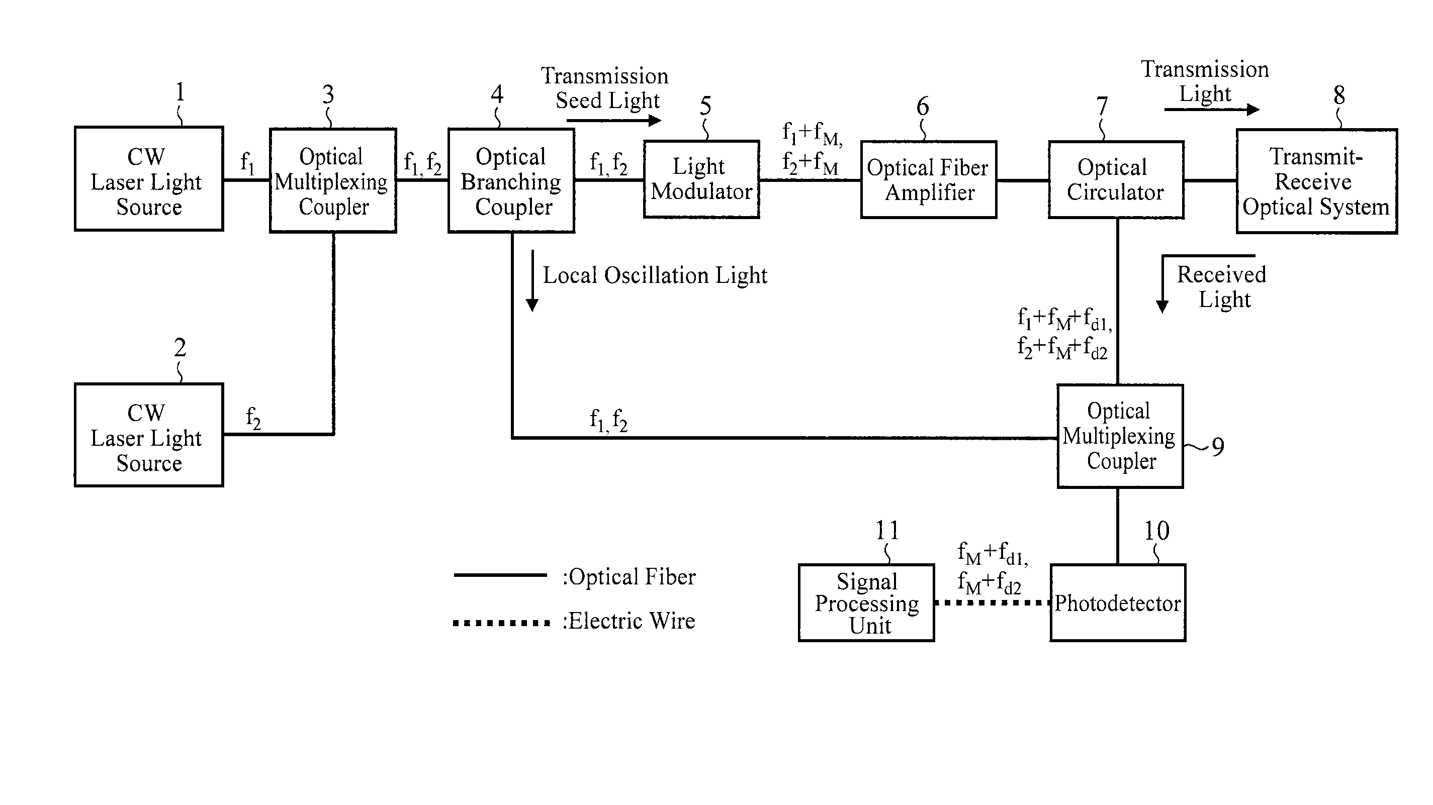
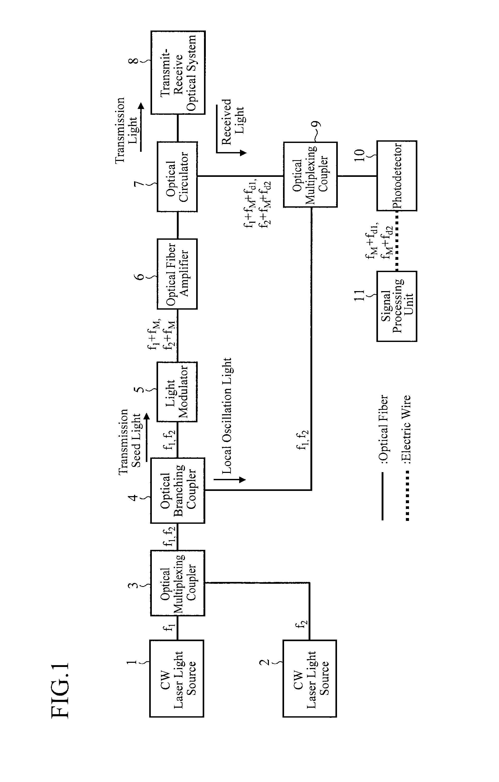
[0019]FIG. 1 is a block diagram showing a configuration of a lidar of an embodiment 1 in accordance with the present invention.

[0020]In FIG. 1, a CW laser light source 1 is a light source that oscillates CW (Continuous Wave) laser light with frequency f1.

[0021]A CW laser light source 2 is a light source that oscillates CW laser light with frequency f2.

[0022]It is assumed here that the frequencies f1 and f2 of the CW laser light rays oscillated by the CW laser light sources 1 and 2 are within the gain band of an optical fiber amplifier 6, and that the difference between the frequency f1 and the frequency f2 is greater than the gain bandwidth of stimulated Brillouin scattering occurring in an optical fiber.

[0023]An optical multiplexing coupler 3 is an optical element that mixes the CW laser light with frequency f1 oscillated by the CW laser light source 1 and the CW laser light with frequency f2 oscillated by the CW laser light source 2. Incidentally, the optical multiplexing coupler ...

embodiment 2

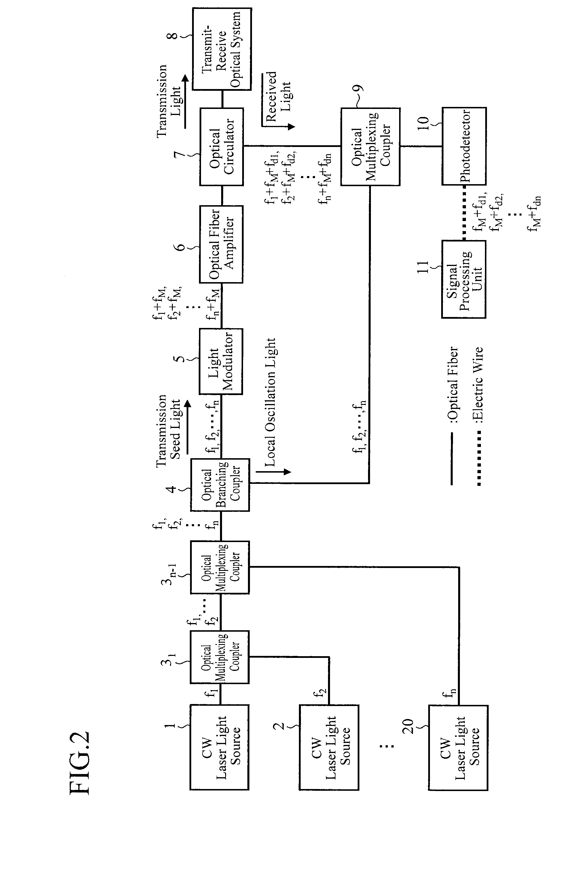
[0092]The foregoing embodiment 1 shows an example comprising the two CW laser light sources 1 and 2 that oscillate the CW laser light rays with wavelengths different from each other. However, the number of the wavelengths of the laser light can be increased as long as the gain of the optical fiber amplifier 6 is large enough and the power of the laser light does not destroy the optical fibers or the optical elements on the transmitting optical path.

[0093]In the present embodiment 2, a lidar comprising n CW laser light sources will be described.

[0094]FIG. 2 is a block diagram showing a configuration of a lidar of the embodiment 2 in accordance with the present invention. In FIG. 2, since the same reference numerals as those of FIG. 1 designate the same or like components, their description will be omitted.

[0095]A CW laser light source 20 is a light source that oscillates CW laser light with frequency fn.

[0096]The example of FIG. 2 comprises n (n=1, 2, . . . , n) CW laser light source...

embodiment 3

[0110]FIG. 3 is a block diagram showing a configuration of a lidar of an embodiment 3 in accordance with the present invention. In FIG. 3, since the same reference numerals as those of FIG. 1 designate the same or like components, their description will be omitted.

[0111]The optical branching coupler 21 is an optical element that splits the CW laser light with frequency f1 oscillated by the CW laser light source 1 into two parts, and that supplies first CW laser light to a light modulator 23 as the transmission seed light and second CW laser light to an optical multiplexing coupler 26 as the local oscillation light.

[0112]The optical branching coupler 22 is an optical element that splits the CW laser light with frequency f2 oscillated by the CW laser light source 2 into two parts, and that supplies first CW laser light to a light modulator 24 as the transmission seed light and second CW laser light to an optical multiplexing coupler 26 as the local oscillation light.

[0113]Incidentally...


PUM


Abstract

A lidar includes CW laser light sources that oscillate CW laser light rays with wavelengths different from each other; an optical multiplexing coupler that mixes the CW laser light rays oscillated by the CW laser light sources; an optical branching coupler that splits the CW laser light passing through the mixing by the optical multiplexing coupler; a light modulator that modulates first CW laser light split by the optical branching coupler; and an optical fiber amplifier that amplifies the laser light modulated by the light modulator, in which a transmit-receive optical system irradiates a target with the laser light amplified by the optical fiber amplifier, and receives scattered light of the laser light by the target.

Description

TECHNICAL FIELD[0001]The present invention relates to a lidar for measuring the position or velocity of a target by using an optical fiber as a propagation path of light within the lidar, by emitting laser light into an atmosphere, by receiving scattered light of the laser light by a target (such as the atmosphere, particles and aerosol in the atmosphere, a flying object and a building), and by detecting the Doppler shift the scattered light undergoes.BACKGROUND ART[0002]The following Non-Patent Document 1 discloses a lidar that generates pulses of transmission light by using as a light modulator an acoustooptic (AO) device driven by a pulse.[0003]In addition, the following Patent Document 1 discloses a lidar that uses an optical fiber as a propagation path of light within the lidar. Considering that the peak power of the transmission light is limited owing to nonlinear optical effect called stimulated Brillouin scattering that occurs within the optical fiber, the lidar implements h...

Claims


Application Information

Patent Timeline
Patent Type & Authority Applications(United States)
IPC IPC(8): G01S17/10G01S17/26G01S17/18
CPCG01S17/102G01S7/4815G01S7/4818G01S17/58G01S17/95G01S17/18G01S7/484G01S17/26Y02A90/10
Inventor SAKIMURA, TAKESHIYANAGISAWA, TAKAYUKIKAMEYAMA, SHUMPEIANDO, TOSHIYUKIHIRANO, YOSHIHITO
Owner MITSUBISHI ELECTRIC CORP
Why Eureka
Try Eureka