Supercharge Your Innovation With Domain-Expert AI Agents!

Method and system for detecting an object or body based on changes in signal phases

a signal phase and object technology, applied in the field of method and system for detecting objects or bodies based on changes in signal phases, can solve the problems of inability to accurately detect the distance between a user and the control device (e.g., keyboard, mouse), and the time taken for the pulse to be transmitted, so as to reduce power consumption

Active Publication Date: 2014-08-21
LOGITECH EURO SA
View PDF6 Cites 1 Cited by
  • Summary
  • Abstract
  • Description
  • Claims
  • Application Information

AI Technical Summary

Benefits of technology

The present invention provides a way to detect the presence of objects or people interacting with a control device by measuring the phase difference caused by them. This helps to reduce power consumption by powering down the control device when no objects are detected and powering it up when an object is detected. This can be achieved without needing multiple devices and by using existing components in the control device.

Problems solved by technology

A limitation with this system is that the time taken for the pulse to be transmitted, reflected back, and received is too short to get accurate readings, as the distance between a user and the control device (e.g., keyboard, mouse) is typically very short.

Method used


Image

  • Method and system for detecting an object or body based on changes in signal phases
  • Method and system for detecting an object or body based on changes in signal phases
  • Method and system for detecting an object or body based on changes in signal phases

Examples


Embodiment Construction

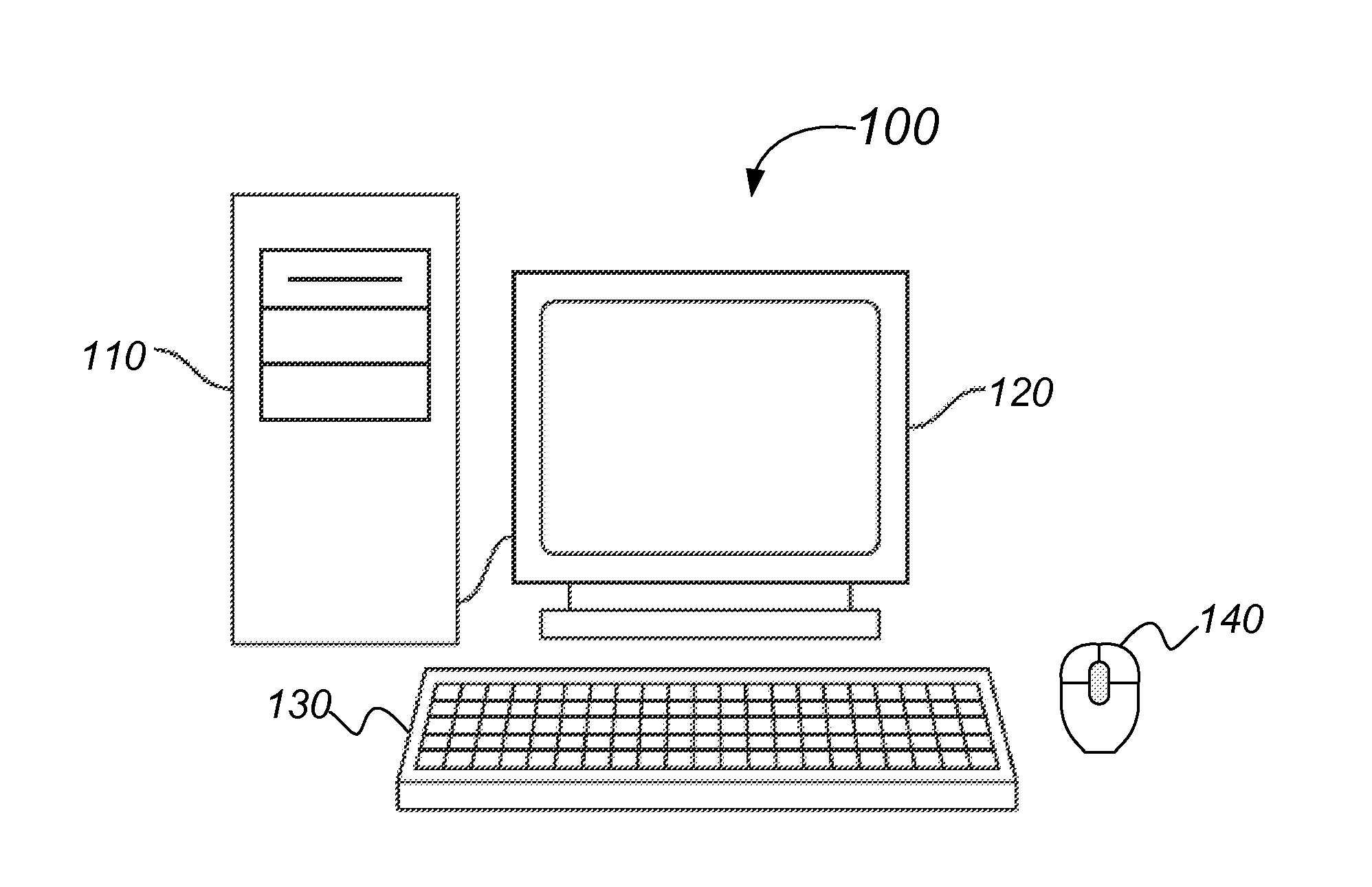
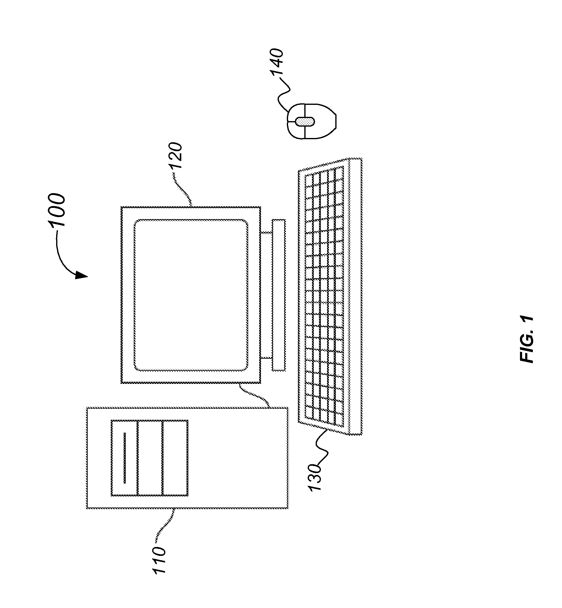
[0014]FIG. 1 is a simplified schematic diagram of a computer system 100 according to an embodiment of the invention. Computer system 100 includes a computer 110, a monitor 120, a keyboard 130, and a control device 140. In some embodiments, the control device 140 is a multi-modal mouse control device. In some embodiments, the control device 140 may refer to either or both the keyboard 130 and a mouse control device. The control device 140 may alternatively be referred to as a multi-modal input device 140. For computer system 100, the multi-modal input device 140 and the keyboard 130 are configured to control various aspects of computer 110 and monitor 120. In some embodiments, the multi-modal input device 140 is configured to provide control signals for page scrolling, cursor movement, selection of on screen items, media control, web navigation, presentation control, and other functionality for computer 110, as further described below. Computer 110 may include a machine readable medi...


PUM


Abstract

Embodiments of the invention are directed to control devices configured for use with computing devices. More specifically, the present invention relates to methods and devices for performing presence detection of an object body near a device. The methods and devices described herein may include comparing a reference signal against an over the air signal to determine whether a phase difference exists between the reference signal and the over the air signal. The existence of a phase difference may be indicative of a object or body in proximity to the device.

Description

BACKGROUND OF THE INVENTION[0001]Presence detection in control devices is currently being used to provide users with benefits that non-presence detecting control devices may lack. For example, the detected presence of a user may cause a backlighting feature of a keyboard or a remote control device to activate. In other examples, the detected presence of the user may activate the power to a wireless control device, such as a mouse or keyboard, such that when the presence of the user is not detected, power consumption is minimized to extend battery life.[0002]One way of detecting the presence of a user would be a pulse radar system that would send a pulse from a transmitter and then measure the amount of time taken for the pulse to be reflected back and received by a receiver coupled to the transmitter. A limitation with this system is that the time taken for the pulse to be transmitted, reflected back, and received is too short to get accurate readings, as the distance between a user...

Claims


Application Information

Patent Timeline
Patent Type & Authority Applications(United States)
IPC IPC(8): H04W24/00
CPCH04W24/00G06F1/3259G06F3/0231G06F3/03543G06F1/3231Y02D10/00H04W24/08
Inventor FORTIN, FREDERICCARIOU, LAURENTCHAZOT, PHILIPPE
Owner LOGITECH EURO SA
Features
  • R&D
  • Intellectual Property
  • Life Sciences
  • Materials
  • Tech Scout
  • Unparalleled Data Quality
  • Higher Quality Content
  • 60% Fewer Hallucinations
Learn More