Peri-vascular tissue ablation catheter with support structures

Active Publication Date: 2014-08-21
ABLATIVE SOLUTIONS INC
View PDF0 Cites 56 Cited by
  • Summary
  • Abstract
  • Description
  • Claims
  • Application Information

AI Technical Summary

Benefits of technology

[0129]Another aspect of the present disclosure is to have a PTAC design with manually expandable guide tubes/needle guiding elements which are advanced outwardly from tubular shafts with distal openings in the distal portion of the body of the PTAC, the tubular shafts and openings providing lateral support for the guide tubes/needle guiding elements to ensure they expand uniformly and symmetrically in a circumferential/lateral distribution. For example, if three guide tubes/needle guiding elements are used, the lateral support will help to ensure that a ˜120 degree angle is maintained between adjacent guide tubes/needle guiding elements, as the guide tubes/needle guiding elements expand outward.
[0130]Another aspect of an embodiment of the PTAC disclosed in the present application is to have an intraluminal centering mechanism (ICM) attached to the guide tubes

Problems solved by technology

The limitation of the needle alone designs are that if small enough needles are used to avoid blood loss following penetration through the vessel wall, then the needles may be too flimsy to reliably and uniformly expand to their desired position.
Without predictable catheter centering and guide tube expansion it may be challenging to achieve accurate and reproducible needle penetration to a targeted depth.
Another limitation of the non-supported

Method used


Image

  • Peri-vascular tissue ablation catheter with support structures
  • Peri-vascular tissue ablation catheter with support structures
  • Peri-vascular tissue ablation catheter with support structures

Examples


first embodiment

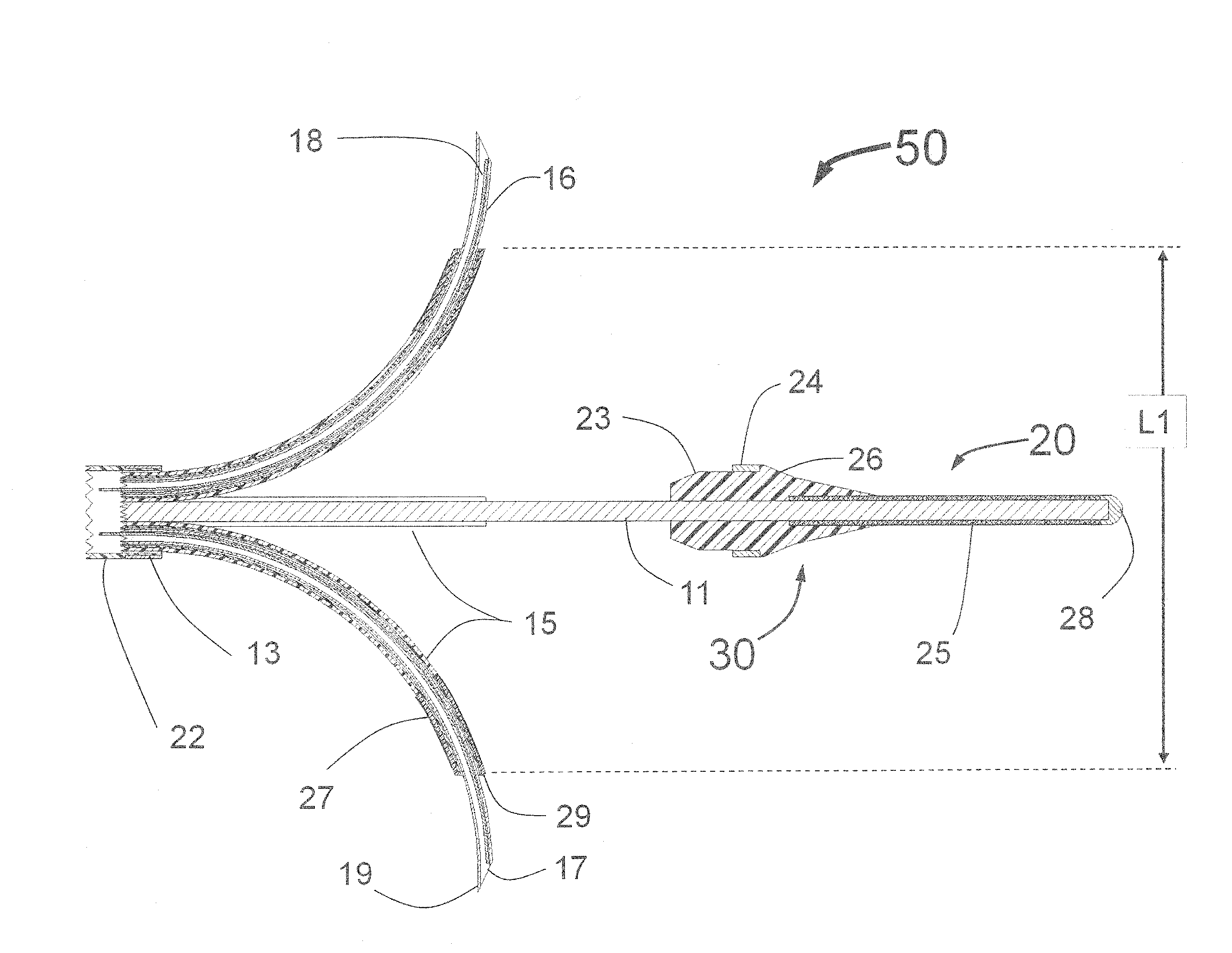
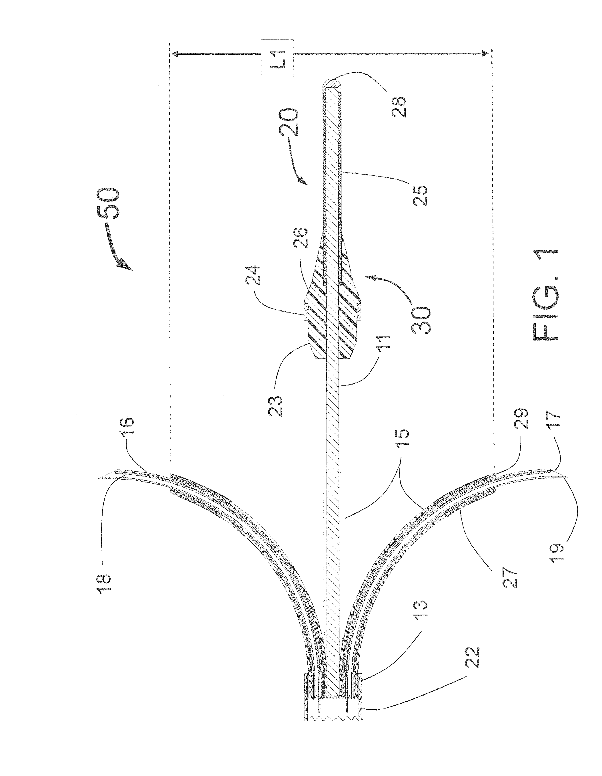
[0294]In a first embodiment the guide tubes 415 are fixedly attached to the proximal conical portion of the balloon 444 and when the balloon 450 is expanded, the guide tubes are moved by the expanding balloon 450, outward until they touch the inside wall of the target vessel. Being attached to an inflated balloon 450 provides both radial and lateral mechanical support for the guide tubes 415. It is envisioned that there are several techniques for creating the structure of guide tubes 415 attached to the balloon 450. Upon expansion, the inflatable balloon 450 deflects the guide tubes outward toward the interior wall of the vessel. This embodiment provides significant enhancement in radial and lateral stability of the guide tubes 415 as compared to the design of the INAS 50 as shown in FIG. 1. This is because the balloon 450 provides significant radial support for the guide tubes 415.

second embodiment

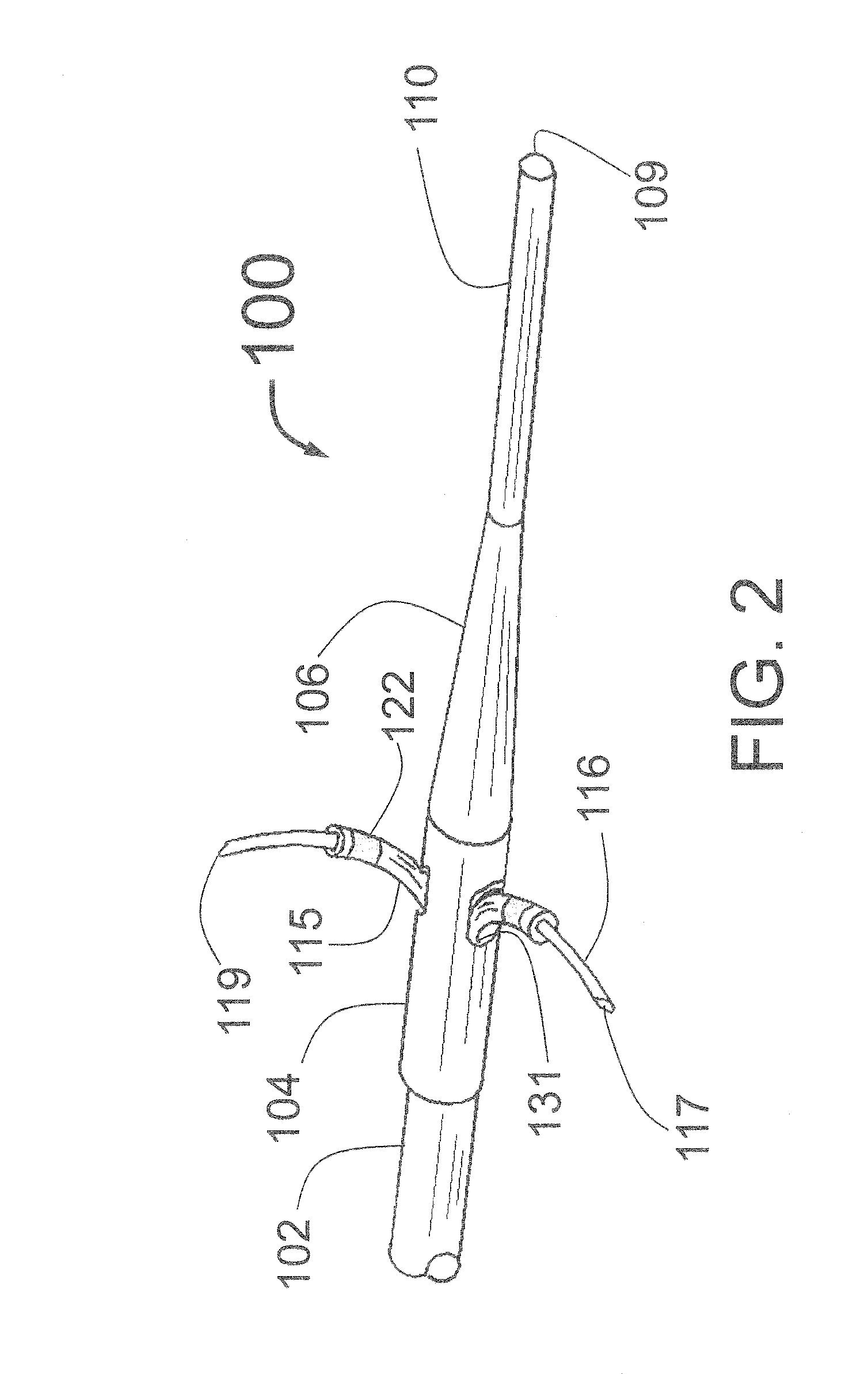
[0295]In a second embodiment, the guide tubes 415 are manually advanced and retracted and the conical portion 444 of the balloon 450 acts as a deflection surface similar to the curved ramp 144 of the PTAC 100 of FIG. 4, the deflection surface deflecting the distally moving guide tubes 415 outward toward the interior wall of the target vessel.

[0296]In some embodiments, it is preferred that the expanded balloon 450 be smaller in diameter than the lumen of the target vessel. This will allow the guide tubes 415 to extend outward beyond the expanded balloon 450. This is shown in FIG. 16, where the guide tubes 415 with radiopaque markers 422 extend beyond the surface of the balloon 450. Thus, when expanded, the balloon 450 would not obstruct blood flow as the blood would be able to flow around the outside of the balloon 450. The balloon 450 can be a non-compliant balloon to ensure there is space between the outside of the balloon and the inside wall of the target vessel for blood to flow....


PUM


Abstract

An intravascular catheter for peri-vascular and/or peri-urethral tissue ablation includes multiple needles advanced through supported guide tubes which expand around a central axis to engage the interior surface of the wall of the renal artery or other vessel of a human body allowing the injection an ablative fluid for ablating tissue, and/or nerve fibers in the outer layer or deep to the outer layer of the vessel, or in prostatic tissue. The system may also include a means to limit and/or adjust the depth of penetration of the ablative fluid into and beyond the tissue of the vessel wall. The catheter may also include structures which provide radial and/or lateral support to the guide tubes so that the guide tubes expand uniformly and maintain their position against the interior surface of the vessel wall as the sharpened injection needles are advanced to penetrate into the vessel wall.

Description

CROSS-REFERENCE TO RELATED APPLICATIONS[0001]This application is a continuation-in-part application of U.S. patent application Ser. No. 13 / 752,062 filed on Jan. 28, 2013, which in turn is a nonprovisional application of U.S. Prov. App. No. 61 / 719,906 filed on Oct. 29, 2012, both applications of which are hereby incorporated by reference in their entireties. Any and all applications for which a foreign or domestic priority claim is identified in the Application Data Sheet as filed with the present application, are hereby incorporated by reference in their entirety under 37 CFR 1.57.FIELD OF THE INVENTION[0002]This invention is in the field of devices to ablate tissue and nerve fibers for the treatment of hypertension, congestive heart failure, BPH and prostate cancer and other disorders.BACKGROUND OF THE INVENTION[0003]Since the 1930s it has been known that injury or ablation of the sympathetic nerves in or near the outer layers of the renal arteries can dramatically reduce high bloo...

Claims


Application Information

Patent Timeline
IPC IPC(8): A61M5/158
CPCA61M2005/1585A61M5/158A61M25/0084A61M2025/0087A61B18/00A61B2018/00279A61B2218/002A61B2090/3966A61M25/10A61B18/04A61B2018/00404A61B2018/00517A61B2018/00577A61B2018/046A61M25/0662A61B2018/00011
Inventor FISCHELL, DAVID R.FISCHELL, TIM A.RAGLAND, ROBERT RYANKENT, DARRIN JAMESDENISON, ANDY EDWARDJOHNSON, ERIC THOMASBURKE, JEFF ALANHAYDEN, CHRISTOPHER SCOTTFISCHELL, ROBERT E.
Owner ABLATIVE SOLUTIONS INC
Why Eureka
Try Eureka