Cleaning apparatus for filtration layer in seawater infiltration intake

a technology of filtration layer and cleaning apparatus, which is applied in the direction of filtration separation, separation process, treatment involving filtration, etc., can solve the problems of water intake stopping, environmental pollution and biofouling of reverse osmosis membrane, and achieve stable implementation of infiltration intake, reduce the impact of surrounding environment, and prevent clogging

Active Publication Date: 2014-08-28
HITACHI ZOSEN CORP +1
View PDF4 Cites 13 Cited by
  • Summary
  • Abstract
  • Description
  • Claims
  • Application Information

AI Technical Summary

Benefits of technology

[0019]The present invention is able to reduce the impact on the surrounding environment with the agitation device and the suction and discharge device, which are operated in the turbid water intake pit, suction the clogging substances trapped in the surface layer and discharge them to outside of the system. The present invention is also able to prevent clogging by removing the clogging substances in a suitable and timely manner, thereby making installation possible in an ocean area where there is little movement of seawater. Therefore, even in cases where the seawater infiltration rate is increased as high as possible under 400 m / day, this infiltration rate can be maintained, enabling a stable implementation of infiltration intake with a water intake surface area which is greatly reduced in comparison to the prior art.

Problems solved by technology

However, when employing the direct water intake method, debris, sediments, and living organisms are all taken in at the same time as the water, and thus there are cases in which water intake has to be stopped, for example, when there is abnormal adhesion of jellyfish or algal blooms, oil spill accidents, and increased turbidity due to high waves.
Furthermore, when chlorine is introduced into seawater to prevent the adhesion of marine life when employing the direct water intake method, there arise problems of environmental pollution and biofouling of reverse osmosis membranes, which are remotely caused by chlorine.
Although none of the problems of the direct water intake method arise when this indirect water intake method is employed, there are problems such as initial high cost and reduced water intake volume due to clogging when clogging substances (e.g., silt) become trapped in the surface layer of the sand filtration layer, and consequently, this method has been slow in achieving widespread use.
However, in the water infiltration intake method disclosed in Patent Reference 1, a large surface area is needed for the intake of a large volume of seawater in a short period of time, because the seawater infiltration intake rate of 1-8 m / day is a very slow filtration rate, and therefore requires a large-scale construction and increased cost.
In addition, since the water infiltration intake method disclosed in Patent Reference 1 utilizes natural waves or currents to remove clogging substances (e.g., silt) which accumulate in the surface layer of the sand filtration layer, an installation site for the water infiltration intake facility is limited to an ocean area where seawater is vigorously moved by currents or waves.
With regard to the second problem, if the sand filtration layer is installed in an ocean area where there is little movement of seawater by waves or currents, it is necessary to clean by artificially removing clogging substances (such as silt) which are trapped in the surface layer of the sand filtration layer.
However, if a pneumatic type cleaning pipe was used in a sand filtration layer in an ocean area where there is little movement of seawater by waves or currents, as shown in FIG. 10, clogging substances (such as silt) which are blown up into the sea above the sand filtration layer and highly concentrated turbid water containing filtration sand can drift into the area surrounding the sand filtration layer, and can become an environmental problem.

Method used


Image

  • Cleaning apparatus for filtration layer in seawater infiltration intake
  • Cleaning apparatus for filtration layer in seawater infiltration intake
  • Cleaning apparatus for filtration layer in seawater infiltration intake

Examples


examples

[0035]Examples of the present invention are described in detail below, with reference being made to FIG. 1 to FIG. 6.

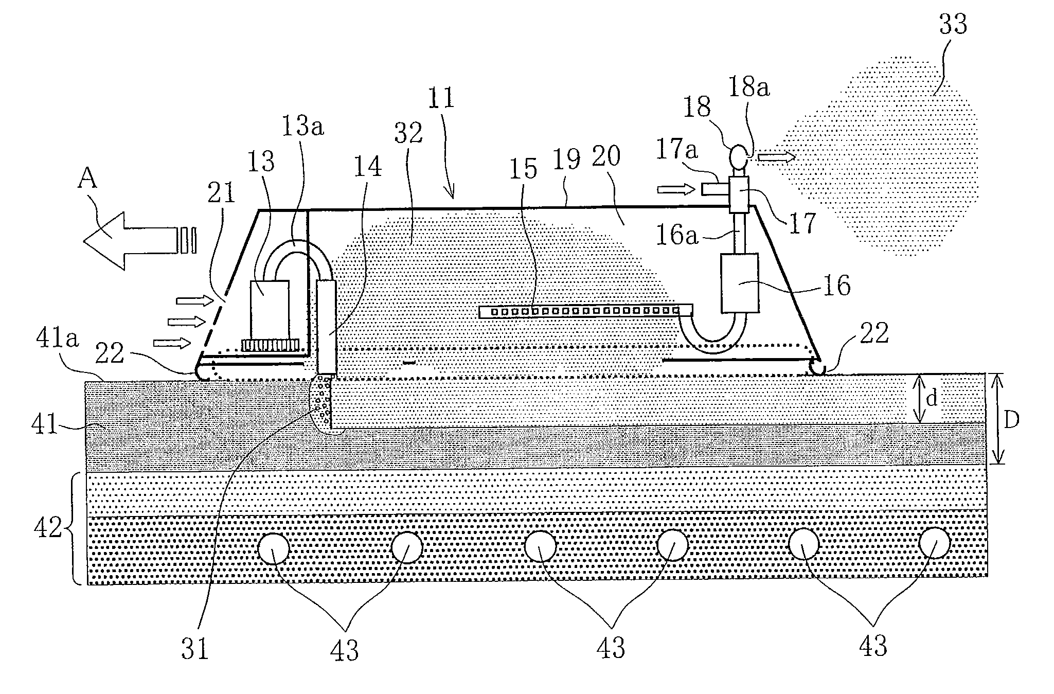
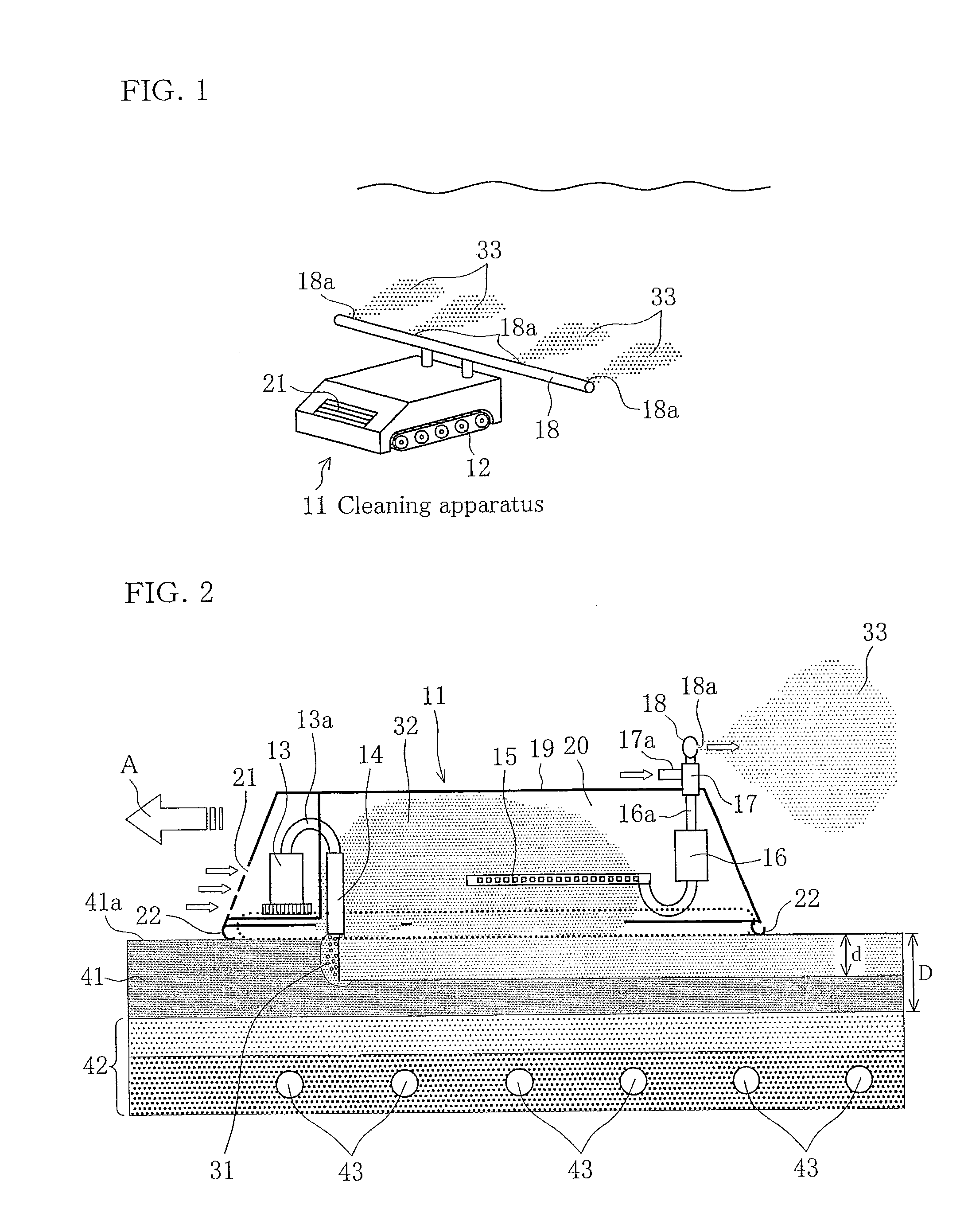
[0036]FIG. 1 is a schematic drawing showing an external view of a cleaning apparatus 11 for a sand filtration layer according to the first example.

[0037]The cleaning apparatus 11 of the first example employs drive wheels 12 with a crawler belt, as a driving device configured to move across the surface of the sand filtration layer. The cleaning apparatus 11 is an automated self-propelled cleaning apparatus which operates on a surface of the sand filtration layer according to a pre-installed program, moving in a horizontal direction at a predetermined speed on a specified surface of the sand filtration layer at a set time, while cleaning an infiltration surface beneath an area where the device passes under predetermined conditions.

[0038]The timing and time-frame for cleaning are optimally set so as not to cause clogging by clogging substances, depending on the water qua...


PUM

PropertyMeasurementUnit
depthaaaaaaaaaa
particle sizeaaaaaaaaaa
particle diameteraaaaaaaaaa

Abstract

To provide a cleaning apparatus suitable for removing clogging substances trapped in a surface layer of a sand filtration layer. A cleaning apparatus equipped with drive wheels serving as a driving device configured to move across a surface of a sand filtration layer. A pump and a jet nozzle are provided as an agitation device configured to agitate a surface layer portion of the sand filtration layer only at a desired depth, and which blows the clogging substances upward into the seawater in a turbid water intake pit together with a filtration sand. A perforated pipe for suctioning turbid water, a pump, an ejector, and a discharge pipe for dilute turbid water are provided as a suction and discharge device configured to suction turbid water blown upward into seawater in the water intake pit by the agitation device, and discharge it to outside of the turbid water intake pit. Prevents clogging by performing a timely cleaning of the sand filtration layer, thereby making it possible to maintain a high-speed seawater infiltration rate for seawater. Impact on the surrounding environment is reduced, because the apparatus suctions turbid water containing clogging substances which is blown upward into the turbid water intake pit, and discharges it to outside of the system.

Description

TECHNICAL FIELD[0001]The present invention relates to a cleaning apparatus for preventing clogging of a sand filtration layer by removing clog-causing substances when they accumulate on a surface layer of the sand filtration layer or are trapped therein, in order to continuously implement a seawater infiltration intake method for the intake of seawater which has been infiltrated in the sand filtration layer.BACKGROUND ART[0002]In seawater desalination plants, which are plants which typically perform seawater intake, reverse osmosis methods which employ reverse osmosis membranes have become commonly used in recent years, instead of evaporation-type water treatment methods. In such reverse osmosis methods, clean seawater with fewer contaminants is sought through pre-treatment to produce fresh water, in order to reduce poor performance resulting from fouling (clogging) of reverse osmosis membranes by contaminants.[0003]As shown in FIG. 7, in an example of a present seawater intake meth...

Claims


Application Information

Patent Timeline
Patent Type & Authority Applications(United States)
IPC IPC(8): B01D24/46C02F1/00
CPCB01D24/4626C02F1/004C02F2103/08E03B3/04Y02W10/37E02F3/8866C02F2303/16E02B3/023B01D24/4621C02F2201/008
Inventor NIIZATO, HIDEYUKIINOUE, TAKAYUKIMUKAI, KIYOKAZUMIMURA, HITOSHI
Owner HITACHI ZOSEN CORP
Why Eureka
Try Eureka