Object information acquiring apparatus

Active Publication Date: 2014-09-04
CANON KK
View PDF9 Cites 4 Cited by
  • Summary
  • Abstract
  • Description
  • Claims
  • Application Information

AI Technical Summary

Benefits of technology

The present invention improves the accuracy of measuring displacement using ultrasound waves in an object information acquiring apparatus. This is achieved by adopting the aperture synthesis method.

Problems solved by technology

Upon calculating the motion of a tissue or hardness of a tissue portion like this, displacement measured with ultrasound waves is frequently used, and therefore in recent ultrasound diagnostic apparatuses, a critical technical issue is the displacement measurement using ultrasound waves.

Method used


Image

  • Object information acquiring apparatus
  • Object information acquiring apparatus
  • Object information acquiring apparatus

Examples


embodiment 1

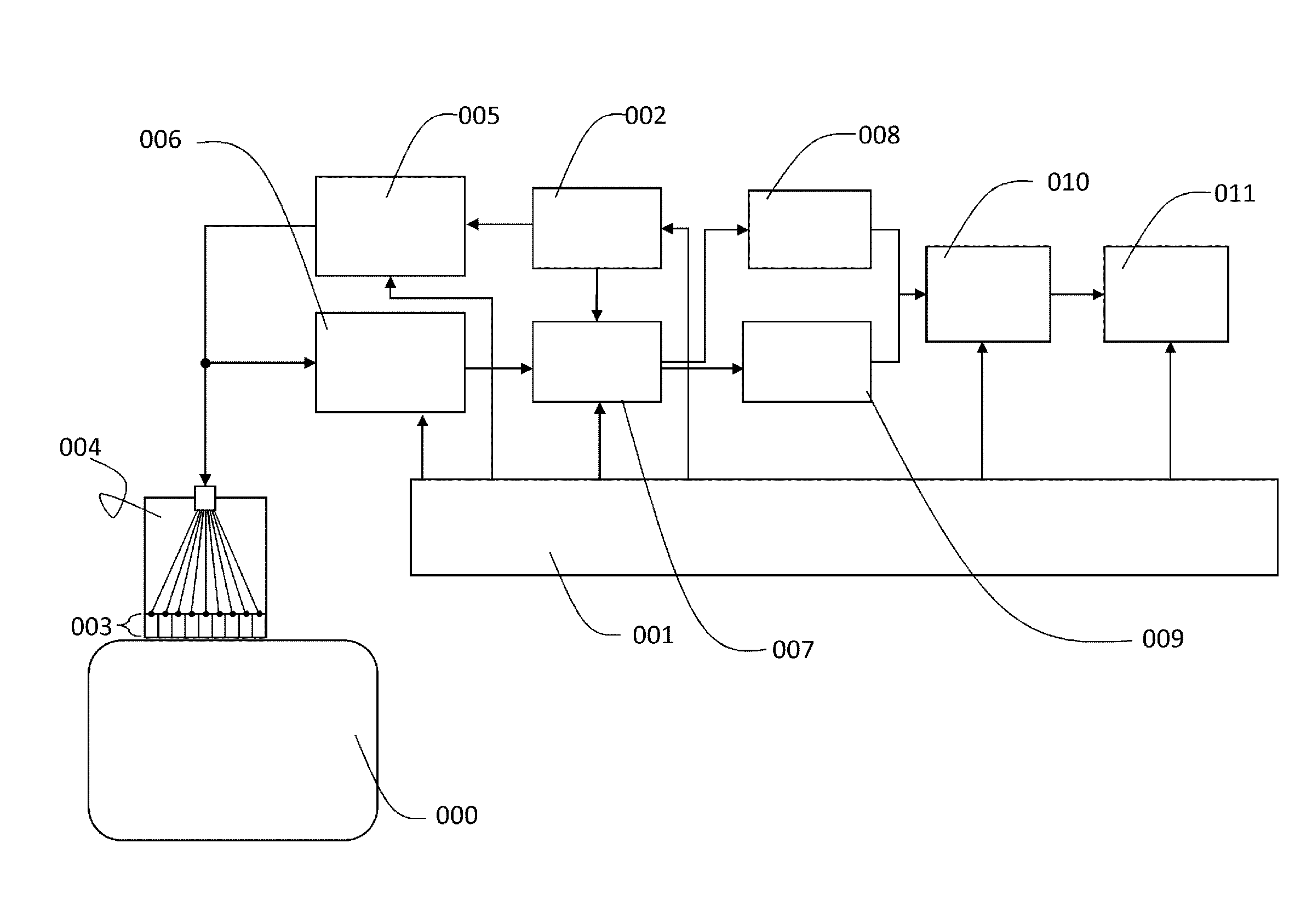
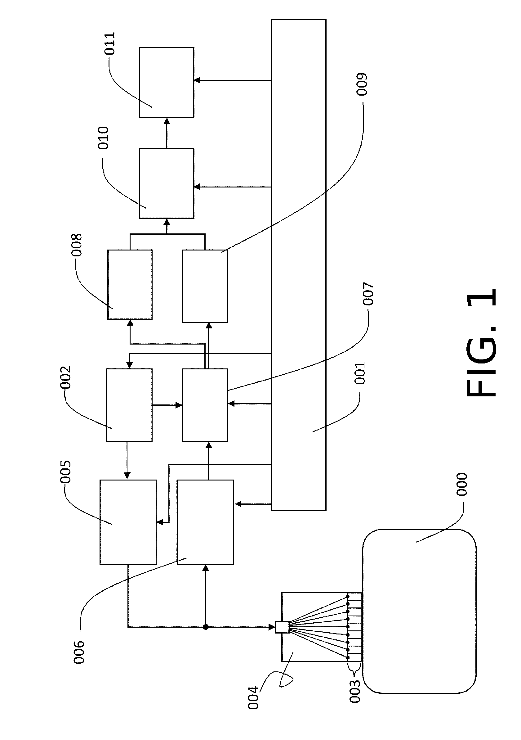
[0036]FIG. 1 is a diagram depicting an overview of a system of an object information acquiring apparatus according to the present invention. A flow of signals and a role of each block in the apparatus of the present invention will be described with reference to FIG. 1, then the respective processing will be described in detail.

[0037](Overview of System and Flow of Signals)

[0038]A code control block 002 generates a code string signal and inputs the code string signal to a transmitting circuit system 005 according to a control signal from a system control unit 001. The transmitting circuit system 005 generates an electric signal having a voltage waveform according to the inputted code string signal. This voltage waveform is converted into an ultrasound wave (elastic wave) by a plurality of ultrasound conversion elements 003, and is transmitted from a probe (transmitting and receiving unit) 004 into an object 000. In the case of ultrasound wave transmission, the system control unit cor...

embodiment 2

[0129]Upon outputting the voltage waveform of which phase is changed according to the code string signal, the voltage waveform need not always have one wavelength for one code. In other words, the voltage waveform of which phase is changed may have a length of a plurality of wavelengths.

[0130]If a voltage waveform having a plurality of wavelengths is used like this, the SN ratio and displacement estimation accuracy further improve, compared with the case of using the voltage waveform having one wavelength.

[0131]However, as the length of the voltage waveform increases, the spatial resolution to estimate displacement decreases, therefore it is desirable to keep the length of the voltage waveform to be a length less than or equal to the spatial resolution determined by the above mentioned spatial low pass filter.

embodiment 3

[0132]Each value of the code string signal may be applied to a plurality of elements, instead of one element at a time.

[0133]An example of applying each value of the code string signal to a plurality of elements will be described with a reference to FIG. 6. The code string signal used here is the same as that described in the above example.

[0134]In this case, the elements of the transmitting and receiving unit are grouped as shown in FIG. 6. An element 601 to an element 603 constitute an element group A (621), an element 604 to an element 606 constitute an element group B (622), an element 607 to an element 609 constitute an element group C (623), and an element 610 to an element 612 constitute an element group D (624).

[0135]The code string signal transmitted from the code control block 002 is inputted to the transmitting circuit system 005. In the transmitting circuit system 005, the voltage waveform is transmitted to twelve elements, that is the element 601 to the element 612.

[013...


PUM


Abstract

Disclosed is an apparatus that transmits an elastic wave to an object and receives a reflected wave, this apparatus including: a transmitting and receiving unit having elements for converting an elastic wave to an electric signal, and being arranged at least in one direction; an element controlling unit that inputs an electric signal to the element and causes the element to transmit an elastic wave; and a detecting unit that detects a reflected wave to be received by the element, wherein the electric signal to be inputted to the element is an encoded pulse signal encoded among the elements, and the detecting unit decodes the reflected wave and executes at different time points aperture synthesis processing of synthesizing the decoded reflected wave with respect to the intersections of two axes at different time points.

Description

TECHNICAL FIELD[0001]The present invention relates to an object information acquiring apparatus using an ultrasound wave.BACKGROUND ART[0002]Generally an ultrasound diagnostic apparatus not only displays an ultrasonographic image (a B-mode image) which visualizes a structure inside a bio-tissue based on a reflected wave that shows acoustic impedance distribution in tissue, but also has a function to visualize the blood flow and motion of tissues.[0003]Also recently estimating the hardness of a tissue portion in use of ultrasound waves has begun, and data thus obtained is used for diagnosing tissue. A strain inside the tissue, generated by such a method as applying static pressure from the surface of the body or applying excitation using a relatively low frequency ultrasound waves, is measured using ultrasound waves, and hardness of the tissue is estimated based on the amount of the strain. To calculate this strain, the displacement distribution of each point, measured with the ultra...

Claims


Application Information

Patent Timeline
IPC IPC(8): G01N29/36G01N29/34G01N29/44
CPCG01N29/36G01N29/34G01N29/44A61B8/485G01S15/8959G01S15/8977G01S7/52042G01S7/5209G01S7/52085A61B8/5207
Inventor NAGAE, KENICHIKONDO, KENGOYAMAKAWA, MAKOTOSHIINA, TSUYOSHI
Owner CANON KK
Why Eureka
Try Eureka